
Jenny
Curtiss Jenny All Done!
14 - March - 2012 - 20:30
At long last, another model can be called done!
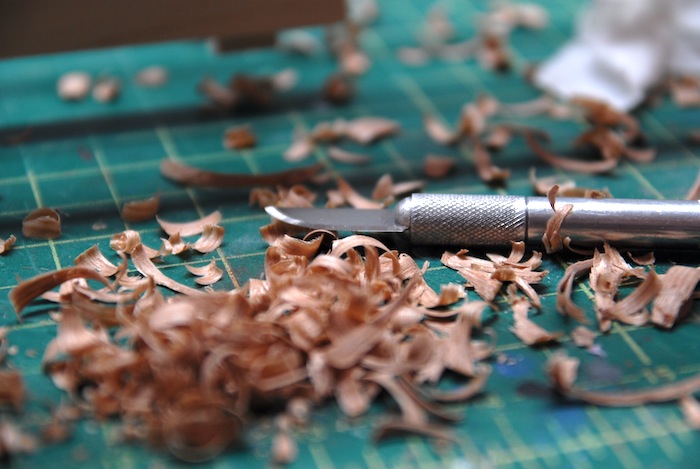
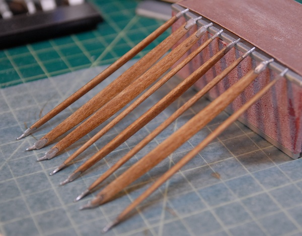
Since the last blog post, I've moved, gained a new (and improved!) model work space and managed to finish both the model and a simple base for it. Picking up where I last left off, I had a bit of carving to do to shape the propeller. It was constructed from a bunch of thin walnut strips, glued together to make a block that was thick enough to carve the prop from.
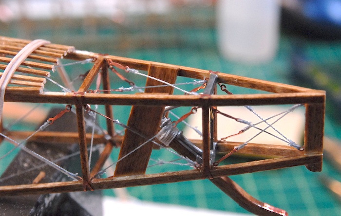
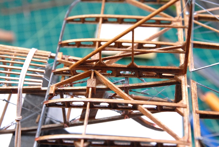
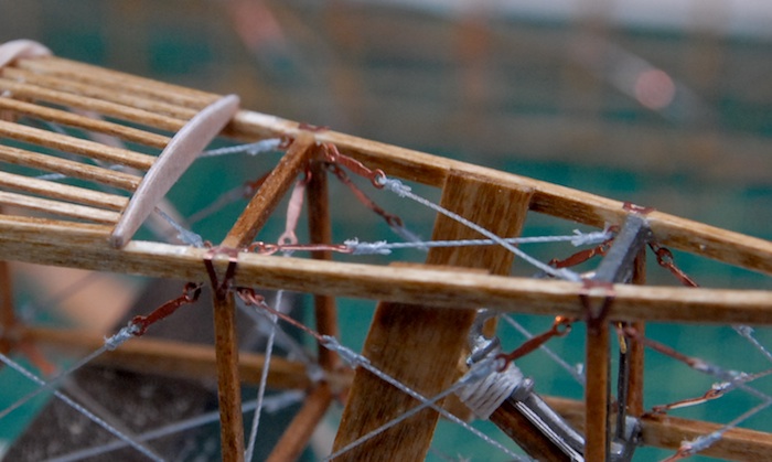
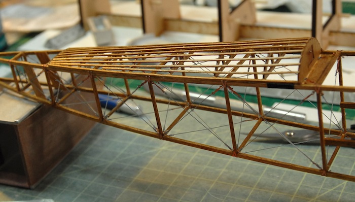
At the same time, I managed to start the wing rigging. There were a TON of wires on each side, which, on the real planes, kept the wings from folding up when flying.
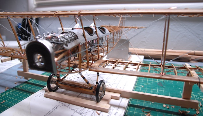
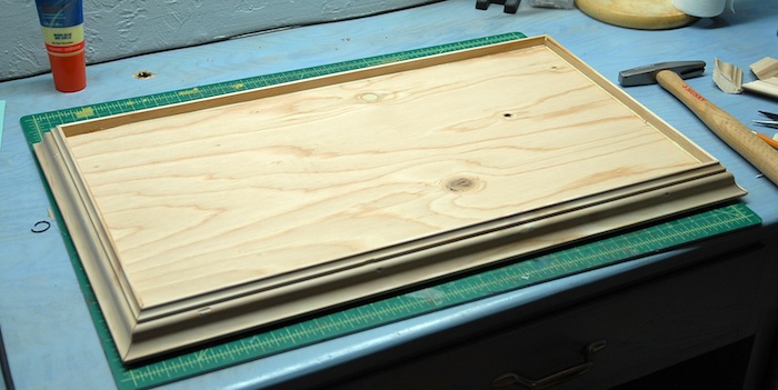
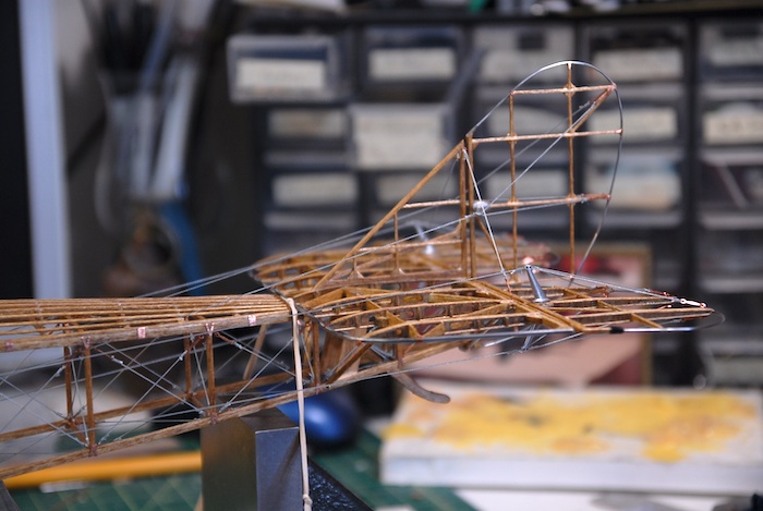
Once the wings were rigged up, there were a few extra wires to add on, the finished prop to attach and the plane was done! Next up was to put together a base of some sort to attach it to. I wanted some sort of base, so that I could fasten the model to it and thereby make it much easier to transport, less likely to damage and maybe add a bit of visual appeal. I headed to Home Depot and grabbed some plywood and wooden molding. Some quality time with a saw, and a few small nails, and I had myself the makings of a base. board.
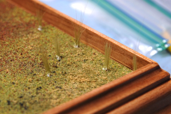
I decided that I wanted a simple covering for the base that was stain on the molding (that matched the plane) and a grass-like covering for the plywood. I grabbed some common model train terrain supplies and gave it a shot. This wasn't something that I had ever tried before, so I pretty much just winged it.
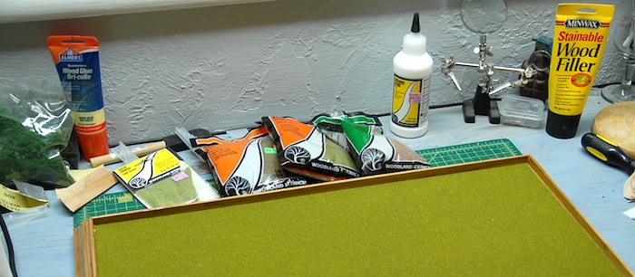
My shot at little tufts of grass:
 \
\
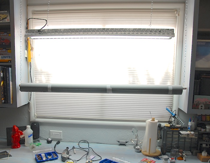
With that done, I was ready to photograph it. The challenge here was that this was pretty much the largest model I have ever made. I decided that instead of using my regular background, which is just a couple of large sheets of paper, I should instead order a proper roll of backdrop paper, which was 53 inches wide and way longer than I'll ever need. This presented me with the challenge of how to hang the roll up while shooting my photos without having to purchase a bunch of backdrop stands. After another trip to Home Depot, I came home with a broom handle and a length of light chain. A few hooks screwed into the broom handle (cut down by a few inches) and hooks into the overhead wood and I've got a removable paper roll hanger.
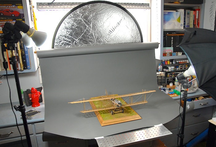
Then, I dragged out the photo equipment and spent an hour or two shooting photos.
So, without further ado, here are the photos of the finished Model Airways Curtiss JN-4D Jenny:
Next up: A Machinen Krieger plastic model...
Since the last blog post, I've moved, gained a new (and improved!) model work space and managed to finish both the model and a simple base for it. Picking up where I last left off, I had a bit of carving to do to shape the propeller. It was constructed from a bunch of thin walnut strips, glued together to make a block that was thick enough to carve the prop from.
At the same time, I managed to start the wing rigging. There were a TON of wires on each side, which, on the real planes, kept the wings from folding up when flying.
Once the wings were rigged up, there were a few extra wires to add on, the finished prop to attach and the plane was done! Next up was to put together a base of some sort to attach it to. I wanted some sort of base, so that I could fasten the model to it and thereby make it much easier to transport, less likely to damage and maybe add a bit of visual appeal. I headed to Home Depot and grabbed some plywood and wooden molding. Some quality time with a saw, and a few small nails, and I had myself the makings of a base. board.
I decided that I wanted a simple covering for the base that was stain on the molding (that matched the plane) and a grass-like covering for the plywood. I grabbed some common model train terrain supplies and gave it a shot. This wasn't something that I had ever tried before, so I pretty much just winged it.
My shot at little tufts of grass:
\With that done, I was ready to photograph it. The challenge here was that this was pretty much the largest model I have ever made. I decided that instead of using my regular background, which is just a couple of large sheets of paper, I should instead order a proper roll of backdrop paper, which was 53 inches wide and way longer than I'll ever need. This presented me with the challenge of how to hang the roll up while shooting my photos without having to purchase a bunch of backdrop stands. After another trip to Home Depot, I came home with a broom handle and a length of light chain. A few hooks screwed into the broom handle (cut down by a few inches) and hooks into the overhead wood and I've got a removable paper roll hanger.
Then, I dragged out the photo equipment and spent an hour or two shooting photos.
So, without further ado, here are the photos of the finished Model Airways Curtiss JN-4D Jenny:
Next up: A Machinen Krieger plastic model...
Almost done...
14 - November - 2011 - 20:12
I'm finally seeing the light at the end of the tunnel on this project. All the big pieces are starting to go together and at the time of this writing all that is left is some rigging and the shaping of the propeller. I suppose I'll also have to fashion some sort of base for the plane to be attached to, in order to help keep it away from damage. Here's what's happened since the last post:
First up, the tail needed to be attached. When I went to fit the tail, I discovered that the turtleback ended a bit too far back on the fuselage, resulting in the tail hanging off the back. This made it so that the rudder wouldn't go on, and clearly, some adjustment would be needed. I brought out the razor saw and trimmed a few millimeters off of the turtle back.
This made some room for the tail to be fitted and the back edge of the vertical stabilizer lined up properly with the back of the fuselage.
Since I cut off the laser-cut part, I needed to craft a new rear rib for the turtle back. Fortunately I had kept the scrap thin plywood that the turtleback parts had come attached to. I snipped off a little bit of that wood, and fashioned a replacement rib. Here you can see it glued in place.
That new piece had to be stained to match the rest of the plane, and then a coat of polyurethane. Next, the tail was glued in place, the rudder attached and the various control lines rigged to connect to the cockpit fittings.
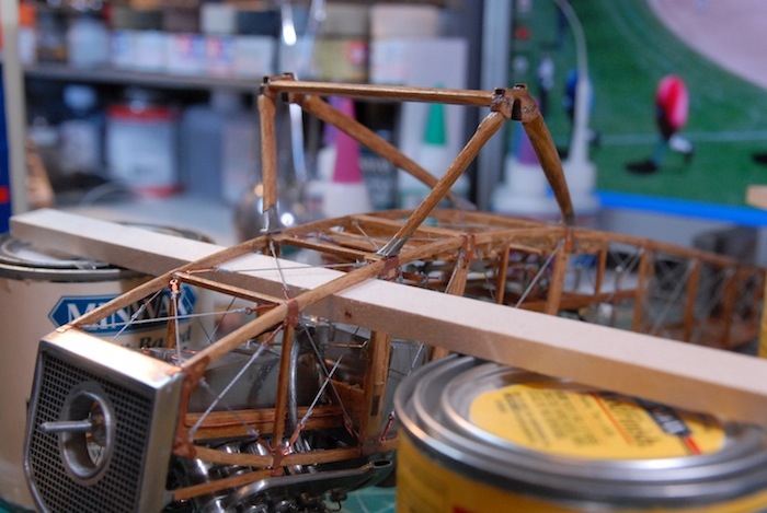
Next up were the lower wings. Below you can see the rough fitting. This mostly just consisted of me drilling out the holes for the connecting pins to go into and then setting the wing in place.
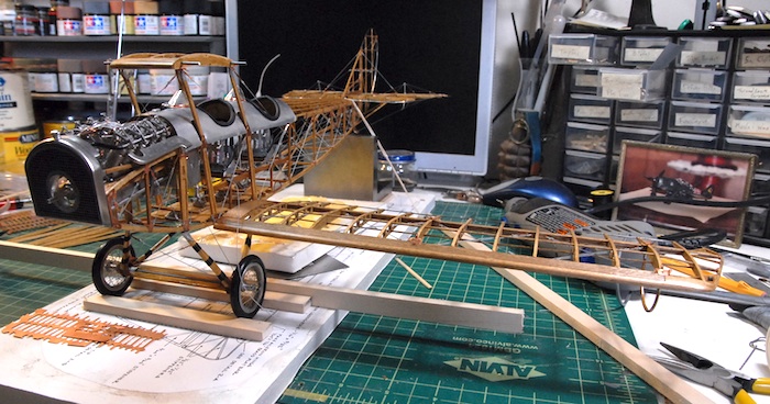
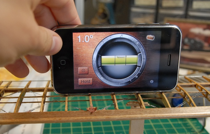
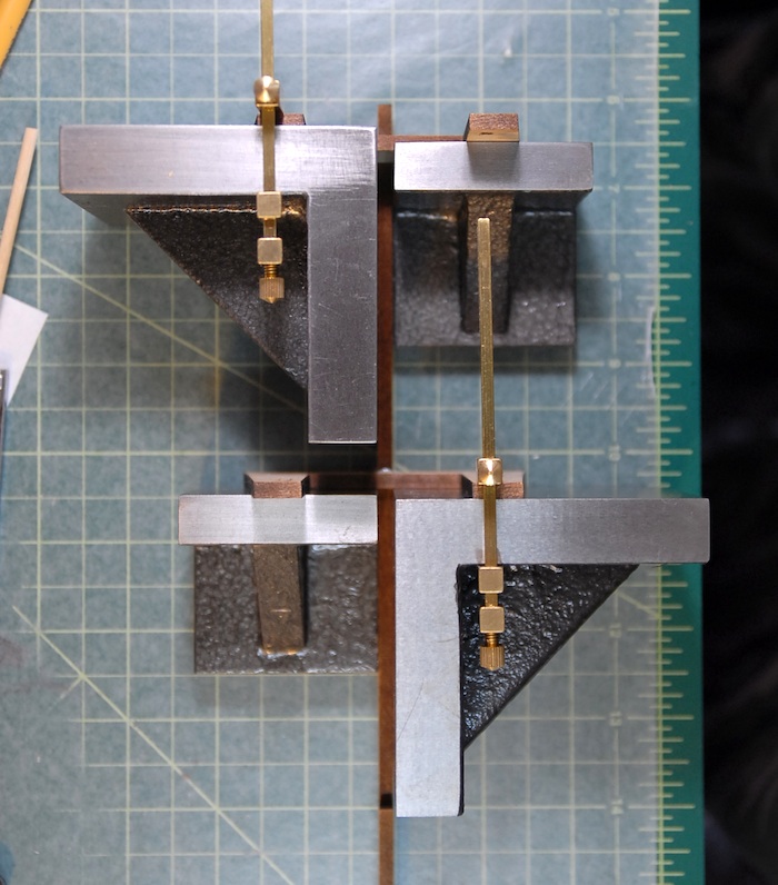
The lower wings are supposed to have one degree of dihedral. In order to get just such a thing, I had to build a little support rig which I could add little shims to until the wing was at just the right angle. Below you can see my high-tech angle measuring method along with my low-tech support and shim method.
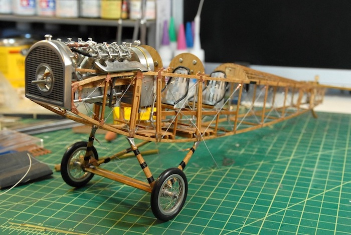
Once the angle of the wings were set, a bit of epoxy held them in place permanently. Next, a similar fitting for the upper wings, although those just sit on top of the inter-plane struts, so were a bit easier to fit. They really just required a boring out of the connection holes, so that the wings could lay at the proper angles.
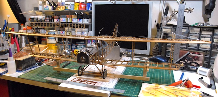
Finally, below you can see the state of the model this evening. The top wings are epoxied in place and the inter-plane struts are glued in place.
Next up: rigging and shaping of the propeller.
First up, the tail needed to be attached. When I went to fit the tail, I discovered that the turtleback ended a bit too far back on the fuselage, resulting in the tail hanging off the back. This made it so that the rudder wouldn't go on, and clearly, some adjustment would be needed. I brought out the razor saw and trimmed a few millimeters off of the turtle back.
This made some room for the tail to be fitted and the back edge of the vertical stabilizer lined up properly with the back of the fuselage.
Since I cut off the laser-cut part, I needed to craft a new rear rib for the turtle back. Fortunately I had kept the scrap thin plywood that the turtleback parts had come attached to. I snipped off a little bit of that wood, and fashioned a replacement rib. Here you can see it glued in place.
That new piece had to be stained to match the rest of the plane, and then a coat of polyurethane. Next, the tail was glued in place, the rudder attached and the various control lines rigged to connect to the cockpit fittings.
Next up were the lower wings. Below you can see the rough fitting. This mostly just consisted of me drilling out the holes for the connecting pins to go into and then setting the wing in place.
The lower wings are supposed to have one degree of dihedral. In order to get just such a thing, I had to build a little support rig which I could add little shims to until the wing was at just the right angle. Below you can see my high-tech angle measuring method along with my low-tech support and shim method.
Once the angle of the wings were set, a bit of epoxy held them in place permanently. Next, a similar fitting for the upper wings, although those just sit on top of the inter-plane struts, so were a bit easier to fit. They really just required a boring out of the connection holes, so that the wings could lay at the proper angles.
Finally, below you can see the state of the model this evening. The top wings are epoxied in place and the inter-plane struts are glued in place.
Next up: rigging and shaping of the propeller.
Engine Is In the Plane!
22 - August - 2011 - 21:24
At long last, tonight I mounted the engine to the fuselage!
Here are a few images showing how I got there.
First, I made a few more 'springs' for the rockers and such.
That gave me the parts to finish up the cylinder assemblies.
Next up was the polishing and mounting of the exhaust headers.
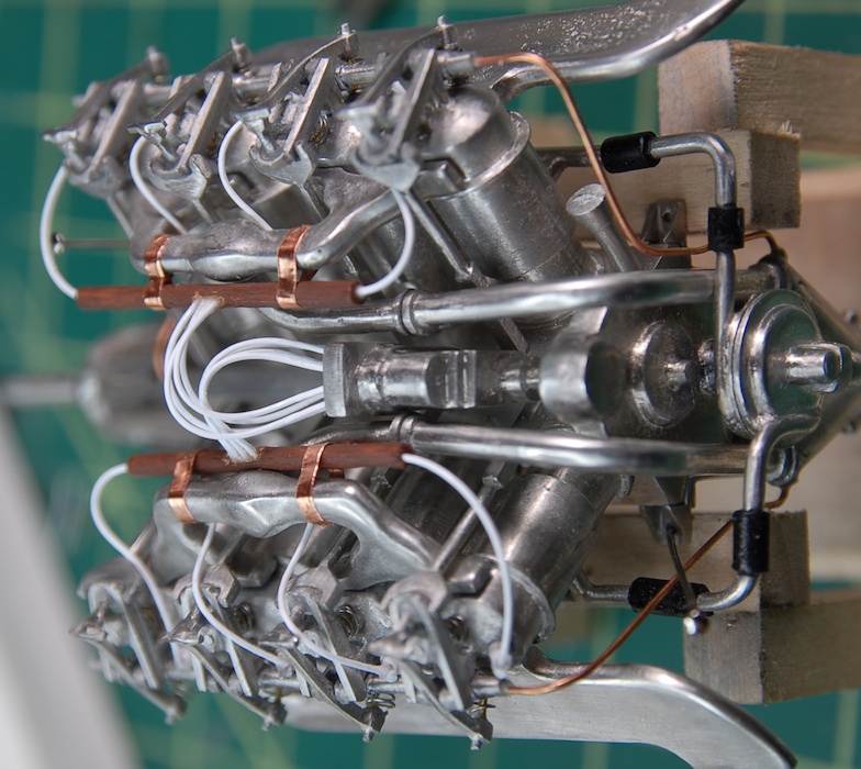
After that was a bit of wiring. This was tricky, as the instructions just mentioned gluing the wires to the spark plugs. Except that, in reality, the wire is very stiff and wouldn't stay glued to the plug tips. Anticipating this issue, I drilled tiny holes in the side of each plug and glued the wire tips into these holes. This was a bit of a pain, but seemed to work out decently. Next up were some little dowels, painted brown, to simulate the fiber tubes that collected and routed the plug wires on their way to the magneto. Finally, there were another eight wires that came out of the dowels and into the magneto.
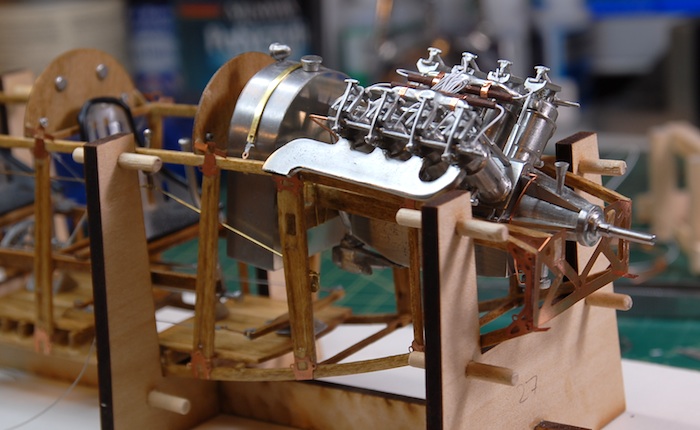
With that step complete, the next step was to mount the engine to the fuselage. While the engine isn't quite complete, all of the remaining steps require that the engine be in the plane, as they mostly involve various tubing and wiring.
Ta Da!
Next up: Wiring, tubes, the radiator and propeller.
Here are a few images showing how I got there.
First, I made a few more 'springs' for the rockers and such.
That gave me the parts to finish up the cylinder assemblies.
Next up was the polishing and mounting of the exhaust headers.
After that was a bit of wiring. This was tricky, as the instructions just mentioned gluing the wires to the spark plugs. Except that, in reality, the wire is very stiff and wouldn't stay glued to the plug tips. Anticipating this issue, I drilled tiny holes in the side of each plug and glued the wire tips into these holes. This was a bit of a pain, but seemed to work out decently. Next up were some little dowels, painted brown, to simulate the fiber tubes that collected and routed the plug wires on their way to the magneto. Finally, there were another eight wires that came out of the dowels and into the magneto.
With that step complete, the next step was to mount the engine to the fuselage. While the engine isn't quite complete, all of the remaining steps require that the engine be in the plane, as they mostly involve various tubing and wiring.
Ta Da!
Next up: Wiring, tubes, the radiator and propeller.
And Picking Back Up Again...
30 - October - 2011 - 20:45
I'm back!
I realize it has been a bit over two months since the last blog update, but I feel as though I have a decent excuse. It turns out that I went and got married about a month ago. So, what with various wedding preparations, the wedding itself and then the honeymoon afterwards, I hardly had any spare moments for working on the ol model. But now that that is all settled and I've got some free time back again, I have finally got a bit of an update.
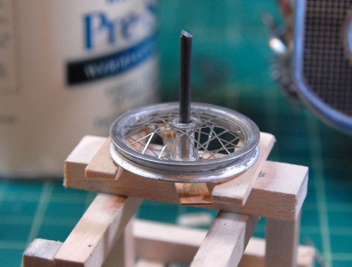
I'm getting into the home stretch now, and the model is beginning to wrap up. I've assembled the wheels, which were a combination of cast hubs and rims and photo-etch spokes. It seems like these sorts of things never fit quite right, and so each wheel has one side that is a little more warped than I would prefer, since the spoke discs were just a hair bigger than they should be. Someone with more patience and some fore knowledge of this might file them all the way around to be just a little smaller, but I'm not and I didn't, so I just bent them into place and called it good.
Below you can see the wheel, and also the little jig that I made from the engine stand and a leftover part of the axle. This setup put the rim and the hub at just the right offset to keep everything centered nicely.
While that was going on, I also was working on putting the gear assembly together. It was a fairly simple setup, with the same fitting of metal parts to wood that was required on the interwing struts that I put together earlier in the build, but haven't fitted to the plane yet. With a bit of sanding and shaping, the various wooden parts were contoured and smoothed. Since this gear was going to have to support the weight of the model, which, with the engine in there, is not insubstantial, I decided to do a little reinforcing of the joints. I drilled a few holes through the joint/hub part (where everything connects) and put some metal rods through that and into each other piece of wood. Hopefully this will add enough strength to keep everything happy attached.
With some O-rings stretched around the wheels for tires and some string wrapped around the landing gear, the plane is finally standing on it's own legs! On a side note, there is a tail skid that Ive finished as well, but I don't have any photos of that handy, so look for that next time.
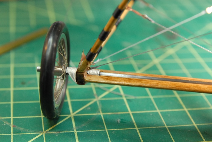
Here is a close up of the wrapped string. On the full-size plane, this added reinforcement to the wood, perhaps keeping it from splitting on landing. On the model, it is just nylon string glued in place with a dab of superglue.
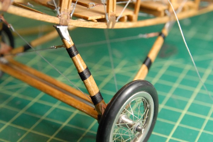
To simulate the simple bungie-cord-like suspension that the plane had, the model has a couple of metal fittings and some wrapped white string. This is actually holding the axle in place, though, so I had to be sure it was good and tight. Once in place, a dab of superglue made sure it wasn't going to go anywhere.
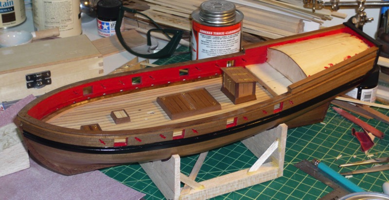
Finally, bringing the blog up to what I was working on just a few hours ago, the aluminum cowl around the cockpit in in progress. Below you can see it bend into place. I used the plank-soaking tube that I made for the Armed Virginia Sloop model (out of some simple PVC pipe) as a form to bend the metal over. The metal just gets bent a bit and then glued into place with the help of a few tabs that wrap under the wooden longerons.
Next up: windshields, cowling trim, and beginning to put all of the parts together!
I realize it has been a bit over two months since the last blog update, but I feel as though I have a decent excuse. It turns out that I went and got married about a month ago. So, what with various wedding preparations, the wedding itself and then the honeymoon afterwards, I hardly had any spare moments for working on the ol model. But now that that is all settled and I've got some free time back again, I have finally got a bit of an update.
I'm getting into the home stretch now, and the model is beginning to wrap up. I've assembled the wheels, which were a combination of cast hubs and rims and photo-etch spokes. It seems like these sorts of things never fit quite right, and so each wheel has one side that is a little more warped than I would prefer, since the spoke discs were just a hair bigger than they should be. Someone with more patience and some fore knowledge of this might file them all the way around to be just a little smaller, but I'm not and I didn't, so I just bent them into place and called it good.
Below you can see the wheel, and also the little jig that I made from the engine stand and a leftover part of the axle. This setup put the rim and the hub at just the right offset to keep everything centered nicely.
While that was going on, I also was working on putting the gear assembly together. It was a fairly simple setup, with the same fitting of metal parts to wood that was required on the interwing struts that I put together earlier in the build, but haven't fitted to the plane yet. With a bit of sanding and shaping, the various wooden parts were contoured and smoothed. Since this gear was going to have to support the weight of the model, which, with the engine in there, is not insubstantial, I decided to do a little reinforcing of the joints. I drilled a few holes through the joint/hub part (where everything connects) and put some metal rods through that and into each other piece of wood. Hopefully this will add enough strength to keep everything happy attached.
With some O-rings stretched around the wheels for tires and some string wrapped around the landing gear, the plane is finally standing on it's own legs! On a side note, there is a tail skid that Ive finished as well, but I don't have any photos of that handy, so look for that next time.
Here is a close up of the wrapped string. On the full-size plane, this added reinforcement to the wood, perhaps keeping it from splitting on landing. On the model, it is just nylon string glued in place with a dab of superglue.
To simulate the simple bungie-cord-like suspension that the plane had, the model has a couple of metal fittings and some wrapped white string. This is actually holding the axle in place, though, so I had to be sure it was good and tight. Once in place, a dab of superglue made sure it wasn't going to go anywhere.
Finally, bringing the blog up to what I was working on just a few hours ago, the aluminum cowl around the cockpit in in progress. Below you can see it bend into place. I used the plank-soaking tube that I made for the Armed Virginia Sloop model (out of some simple PVC pipe) as a form to bend the metal over. The metal just gets bent a bit and then glued into place with the help of a few tabs that wrap under the wooden longerons.
Next up: windshields, cowling trim, and beginning to put all of the parts together!
Engine Updates
07 - August - 2011 - 20:19
As some may have noticed, it has been quite a while since my last update. Those same some might be thinking, "Oh, it just another blog, where the updates get further and further apart." I would like to rebut that with, "Balderdash! The updates have been sparse recently because I am in the midst of wedding planning and have had very little time for modeling, let alone model blogging!"
With that said, I got a bit of time this weekend to do a little bit of modeling, and got the model desk reassembled (the web cam part had been taken apart for wedding related reasons). Once things were back in order, cleaned up and ready to roll, I managed to test out an idea I had been toying around with for some upgrades to the engine, and I think they turned out pretty well. But first, let's get up to date with the state of the model.
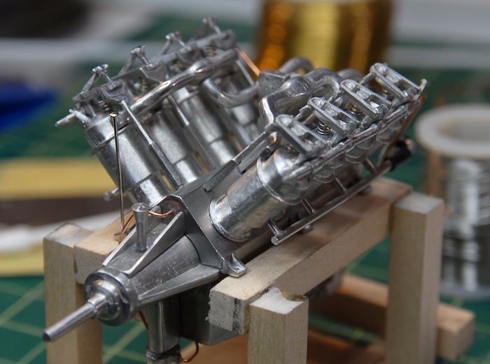
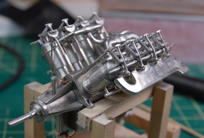
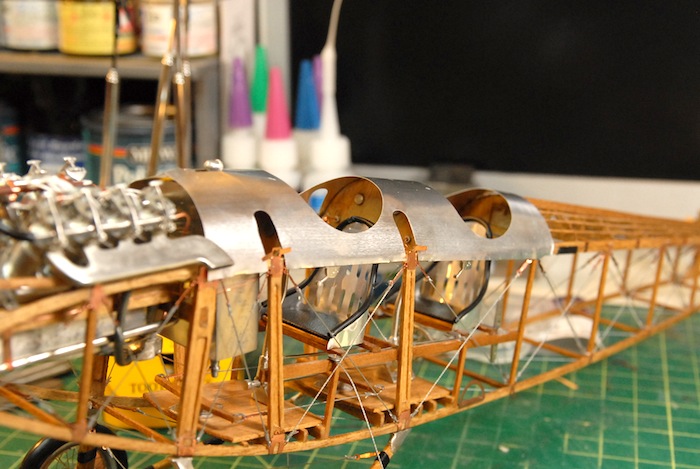
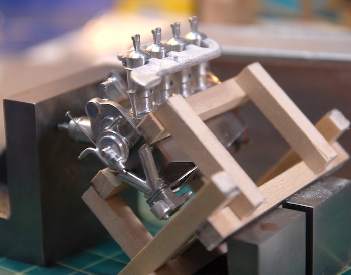
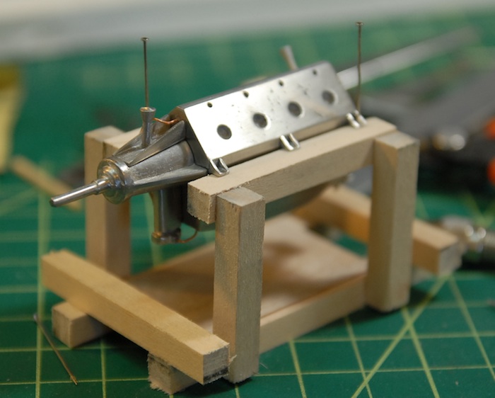
When last I wrote about it, the engine was just beginning assembly, with the large pieces coming together. The next step in the process was to add the cylinders. Here are a few of them, sanded and polished and ready to be epoxied to the engine block.
In order to get them all properly aligned (there is a bit of slop in the attachment points on the engine block), the directions recommended using the intake runner and exhaust headers to insure that everything will align later on. In order to make this easier, I set the whole engine assembly up so that the cylinders balanced on the top while the epoxy set.
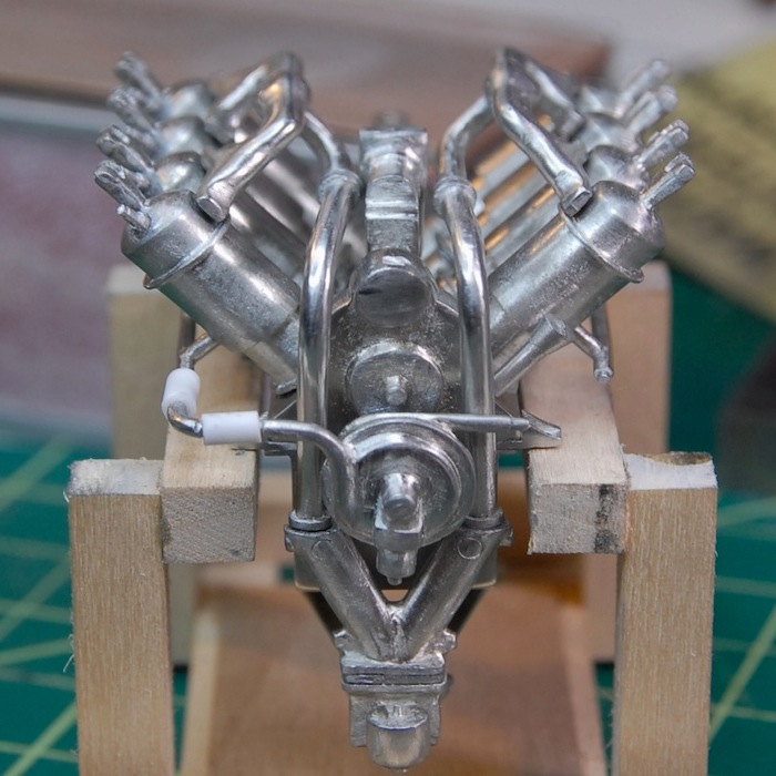
And then the other side:
After the cylinders were all in place, I added on the water inlet piping and the air intakes.
Along with those, there were other miscellaneous pipes that got added. Below you can see the test-fit of the intermediate piping. The kit came with some clear rubber tubing for these parts, but since rubber tubing is a pain to paint, AND I already had various sizes of styrene tubing, I decided to go with the hard styrene tubes, cut to length.
That tubing was then painted black and glued in place on both sides.
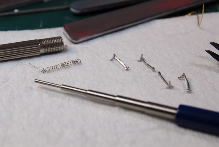
This brings me to the previously-mentioned upgrade. The kit has various pushrods, rockers and such for the top of each cylinder. Cast into two of those parts are 'springs' that I felt were not satisfactory. The castings were shallow and hardly looked like springs at all. So, I decided that I could replace the springs with a center rod and some wound wire that looks like a spring. I wound some very thin wire that I had left from a previous kit around a mandrel tool, and cut some lengths of thicker brass wire for the centers. I cut off the cast springs, filed everything clean and drilled some tiny holes to keep the center rods in place.
Here are the results on my first test cylinder:
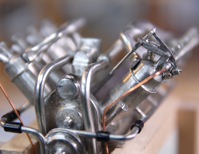
I think these look much more like the real engine. I've got a pile of photo reference of the engine that I have collected and have found it very useful to refer to while building.
And that brings us up to the present. I've got two of the eight cylinders done with the springs, as of tonight, and hopefully I can continue with this during the week and next weekend.The next update should see the engine mounted on the fuselage! Stay tuned!
With that said, I got a bit of time this weekend to do a little bit of modeling, and got the model desk reassembled (the web cam part had been taken apart for wedding related reasons). Once things were back in order, cleaned up and ready to roll, I managed to test out an idea I had been toying around with for some upgrades to the engine, and I think they turned out pretty well. But first, let's get up to date with the state of the model.
When last I wrote about it, the engine was just beginning assembly, with the large pieces coming together. The next step in the process was to add the cylinders. Here are a few of them, sanded and polished and ready to be epoxied to the engine block.
In order to get them all properly aligned (there is a bit of slop in the attachment points on the engine block), the directions recommended using the intake runner and exhaust headers to insure that everything will align later on. In order to make this easier, I set the whole engine assembly up so that the cylinders balanced on the top while the epoxy set.
And then the other side:
After the cylinders were all in place, I added on the water inlet piping and the air intakes.
Along with those, there were other miscellaneous pipes that got added. Below you can see the test-fit of the intermediate piping. The kit came with some clear rubber tubing for these parts, but since rubber tubing is a pain to paint, AND I already had various sizes of styrene tubing, I decided to go with the hard styrene tubes, cut to length.
That tubing was then painted black and glued in place on both sides.
This brings me to the previously-mentioned upgrade. The kit has various pushrods, rockers and such for the top of each cylinder. Cast into two of those parts are 'springs' that I felt were not satisfactory. The castings were shallow and hardly looked like springs at all. So, I decided that I could replace the springs with a center rod and some wound wire that looks like a spring. I wound some very thin wire that I had left from a previous kit around a mandrel tool, and cut some lengths of thicker brass wire for the centers. I cut off the cast springs, filed everything clean and drilled some tiny holes to keep the center rods in place.
Here are the results on my first test cylinder:
I think these look much more like the real engine. I've got a pile of photo reference of the engine that I have collected and have found it very useful to refer to while building.
And that brings us up to the present. I've got two of the eight cylinders done with the springs, as of tonight, and hopefully I can continue with this during the week and next weekend.The next update should see the engine mounted on the fuselage! Stay tuned!
Engine and Deskcam
26 - June - 2011 - 20:49
The Engine!
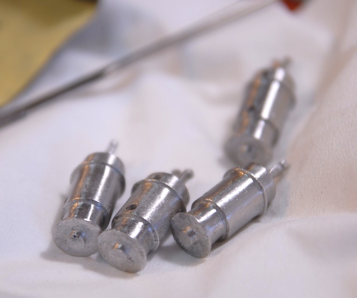
So, I've finally arrived at the reason that I purchased this kit in the first place: the engine. I was completely taken by the engine detail in the product images and wanted a shot at making that same engine and perhaps even improving upon it. The engine, fuel tank and radiator are all mostly made up of cast Britannia metal, which is a mixture of tin, antimony and copper. These parts are all delivered in the kit as raw castings, which gives them a dull surface and sometimes rough details.
Some of the raw engine block castings:
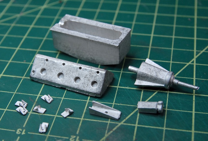
This means that the bulk of the work on the engine is the cleanup, sanding and polishing of these parts, in order to bring them up to a quality finish that complements the rest of the kit. I'm currently wearing through various sanding sticks and a few bits of sandpaper, but I've got some higher grit sandpaper arriving tomorrow, which should make short work of getting these parts in order.
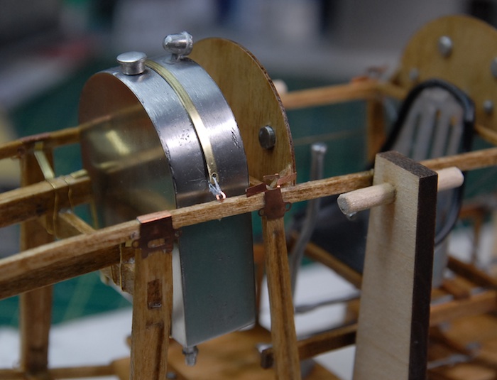
First item to be added was the fuel tank, which was actually a combination of a cast metal frame and photo-etch front and back plates. Here you can see some pictures of the final product after quite a bit of sanding, polishing and a bit of buffing with the ol Dremel. Added to that are three other separately-cast parts, the fuel cap and fuel gauge on the top and sediment trap hanging off of the bottom. This tank is held in place by three brass strips, two cradling it underneath and one over the top.
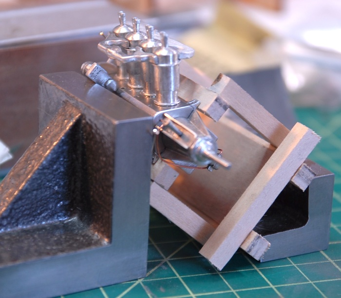
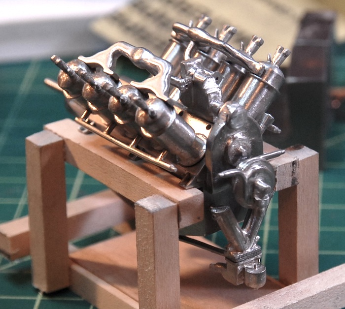
Next up was the engine block itself. For a little while I was working with the block, unattached from the fuselage, but once I started adding more parts, this seemed less and less practical. So, I took a bit of scrap wood and built a little engine stand for it. Here you can see the engine cleaned up a bit and mounted on the temporary stand.
Stay tuned for more additions to the engine as work continues!
Desk Cam Gets a New Computer and Comes Back to Life!
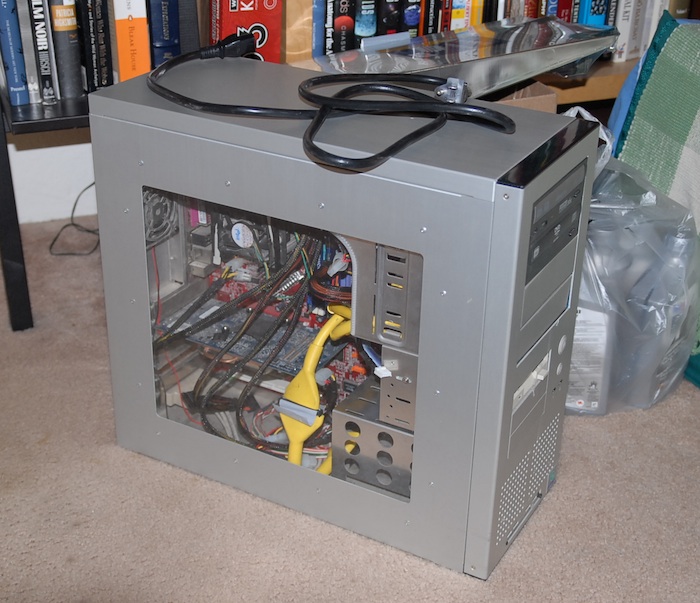
As, I'm sure, many of you noticed (or perhaps didn't notice), the computer that runs my model desk web cam and time-lapse camera managed to die a couple of weeks ago. I think the culprit was the local power company replacing a nearby transformer combined with the computer power supply being on its last legs. Whatever the cause, when the power supply failed it took the motherboard with it, so now all the computer is good for (after I replaced the fried power supply) is moving a bit of air around. Yup, the only things that seem to still work are all of the fans. Alas, poor computer, I knew it well.
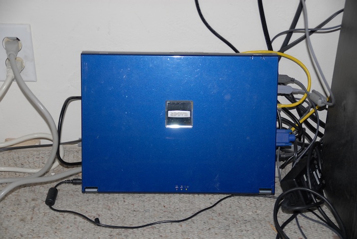
As the untimely demise of my model desk computer left me without a way to run my time-lapse camera and no way to update my desk cam web page, I had to find a new way to run things. Fortunately, I still had my old laptop computer in a closet (actually, the original desk-cam computer ALSO came back to life out of a closet), which I thought might be able to be used in a pinch. So, today I dragged it out, plugged it into all of the appropriate cables, updated and installed various bits of software, and now have a whole new computer running under my model desk!
Rest in Pieces, old model desk computer.
:(
Long live the new model desk computer!
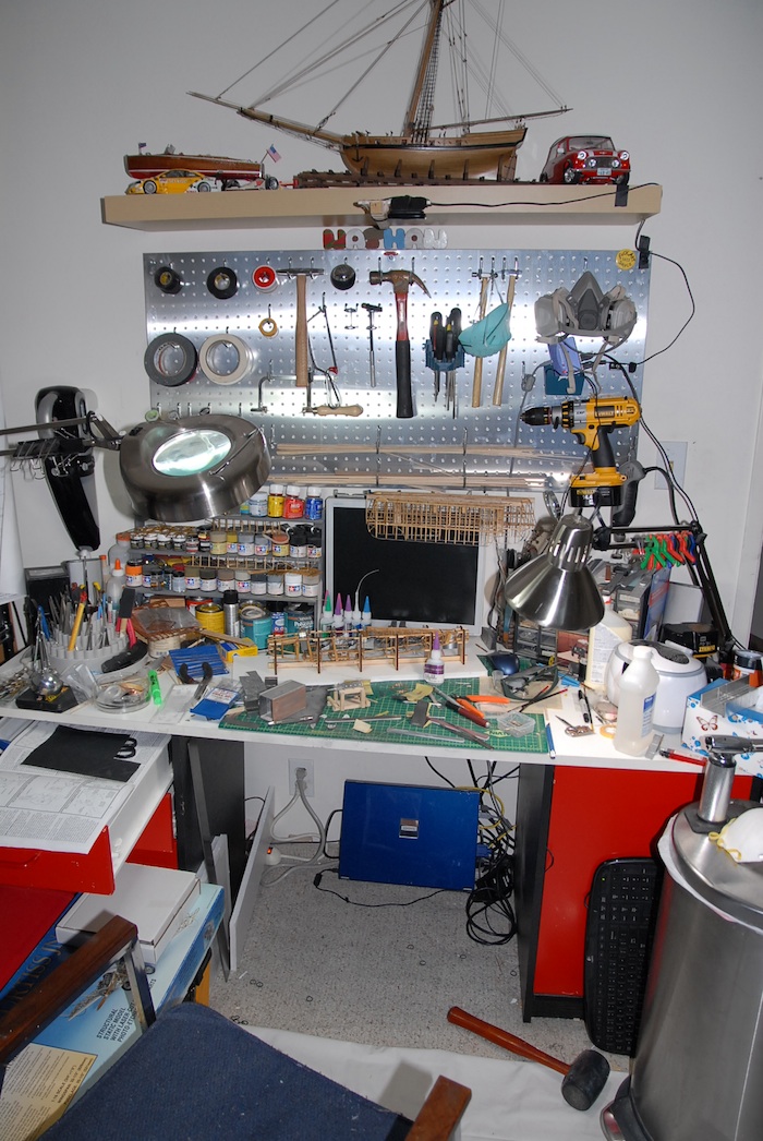
The upside here, is that I've gained a great deal more leg room under the model desk and probably will save a little bit of electricity. Here's the current state of the model desk, including new computer and such:
That's all for now. Tune in next time for more engine progress and hopefully no further news about the model desk computer ;)
So, I've finally arrived at the reason that I purchased this kit in the first place: the engine. I was completely taken by the engine detail in the product images and wanted a shot at making that same engine and perhaps even improving upon it. The engine, fuel tank and radiator are all mostly made up of cast Britannia metal, which is a mixture of tin, antimony and copper. These parts are all delivered in the kit as raw castings, which gives them a dull surface and sometimes rough details.
Some of the raw engine block castings:
This means that the bulk of the work on the engine is the cleanup, sanding and polishing of these parts, in order to bring them up to a quality finish that complements the rest of the kit. I'm currently wearing through various sanding sticks and a few bits of sandpaper, but I've got some higher grit sandpaper arriving tomorrow, which should make short work of getting these parts in order.
First item to be added was the fuel tank, which was actually a combination of a cast metal frame and photo-etch front and back plates. Here you can see some pictures of the final product after quite a bit of sanding, polishing and a bit of buffing with the ol Dremel. Added to that are three other separately-cast parts, the fuel cap and fuel gauge on the top and sediment trap hanging off of the bottom. This tank is held in place by three brass strips, two cradling it underneath and one over the top.
Next up was the engine block itself. For a little while I was working with the block, unattached from the fuselage, but once I started adding more parts, this seemed less and less practical. So, I took a bit of scrap wood and built a little engine stand for it. Here you can see the engine cleaned up a bit and mounted on the temporary stand.
Stay tuned for more additions to the engine as work continues!
Desk Cam Gets a New Computer and Comes Back to Life!
As, I'm sure, many of you noticed (or perhaps didn't notice), the computer that runs my model desk web cam and time-lapse camera managed to die a couple of weeks ago. I think the culprit was the local power company replacing a nearby transformer combined with the computer power supply being on its last legs. Whatever the cause, when the power supply failed it took the motherboard with it, so now all the computer is good for (after I replaced the fried power supply) is moving a bit of air around. Yup, the only things that seem to still work are all of the fans. Alas, poor computer, I knew it well.
As the untimely demise of my model desk computer left me without a way to run my time-lapse camera and no way to update my desk cam web page, I had to find a new way to run things. Fortunately, I still had my old laptop computer in a closet (actually, the original desk-cam computer ALSO came back to life out of a closet), which I thought might be able to be used in a pinch. So, today I dragged it out, plugged it into all of the appropriate cables, updated and installed various bits of software, and now have a whole new computer running under my model desk!
Rest in Pieces, old model desk computer.
:(
Long live the new model desk computer!
The upside here, is that I've gained a great deal more leg room under the model desk and probably will save a little bit of electricity. Here's the current state of the model desk, including new computer and such:
That's all for now. Tune in next time for more engine progress and hopefully no further news about the model desk computer ;)
Cockpit Fittings
19 - June - 2011 - 21:45
Picking up from the last post, the rigging for the fuselage is complete between the tail and the cockpit. I've left off around the cockpit so that it is easier to add various fittings, seats, etc.
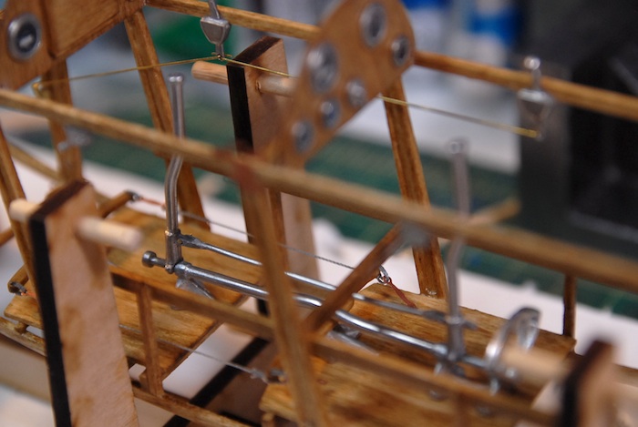
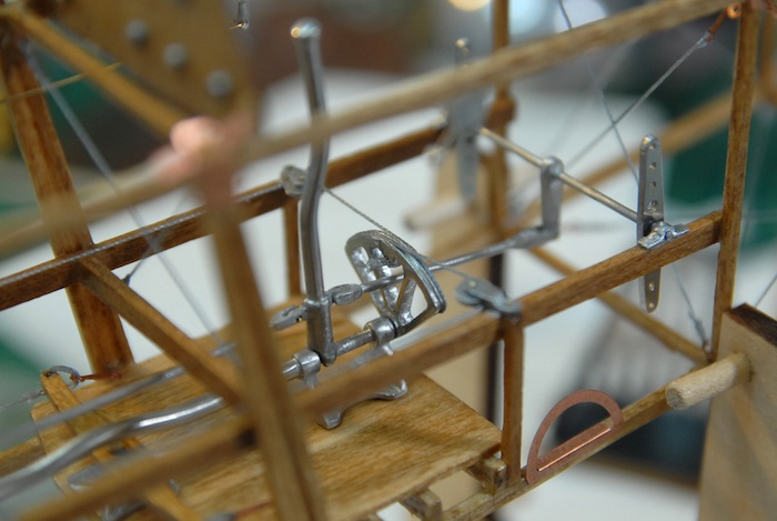
First up in the fittings were the rudder pedals and their connections and mounting points.
Those were followed by the control sticks and their various connections.
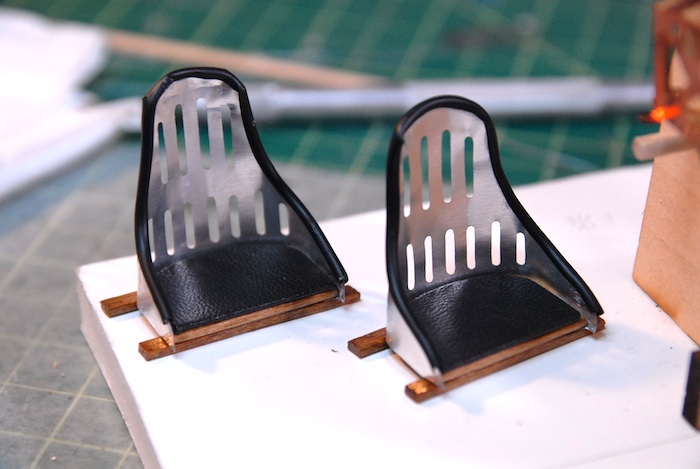
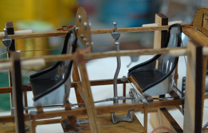
Next up were the seats. The kit came with photo-etch metal backs and wooden seats. The instructions mentioned that the real seats were covered with cloth on the backs and had pads on the seats. I decided that I should add a few of those extras to the seats on my plane. I had some tubing left over from a previous model that I used to line the edges of the seat backs. I feel that this had mixed results and I am not entirely happy with the results. For the cushions, I decided that I would find some leather-like fabric and wrap that around some wood.
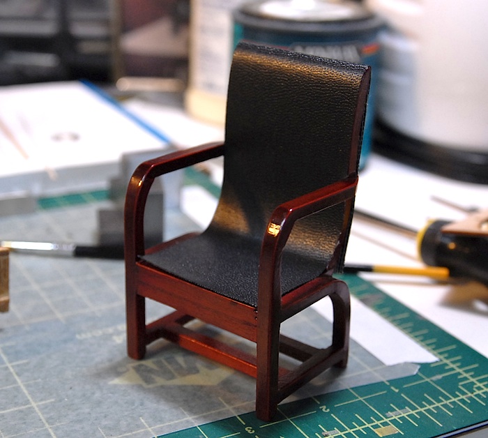
I went to my local hobby shop in search of such a material, but they didn't have anything like that for purchase. But I DID notice a dollhouse chair there, for about $8, that had the type of material that I was looking for. So, I decided that instead of going store to store, looking for what I wanted, I would just buy the chair and strip the cloth off of it.
Behold, the sacrificial chair:
And the end result of my chair-enhancing efforts:
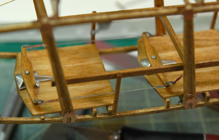
Before installing the chairs into the cockpits, I had to do just a bit of rigging. Here you can see the aileron control wires.
And finally, the seats installed.
With this done, I'm moving on to the engine and fuel tank. It's a fun-filled world of cast metal and sanding/polishing. Stay tuned for further adventures!
First up in the fittings were the rudder pedals and their connections and mounting points.
Those were followed by the control sticks and their various connections.
Next up were the seats. The kit came with photo-etch metal backs and wooden seats. The instructions mentioned that the real seats were covered with cloth on the backs and had pads on the seats. I decided that I should add a few of those extras to the seats on my plane. I had some tubing left over from a previous model that I used to line the edges of the seat backs. I feel that this had mixed results and I am not entirely happy with the results. For the cushions, I decided that I would find some leather-like fabric and wrap that around some wood.
I went to my local hobby shop in search of such a material, but they didn't have anything like that for purchase. But I DID notice a dollhouse chair there, for about $8, that had the type of material that I was looking for. So, I decided that instead of going store to store, looking for what I wanted, I would just buy the chair and strip the cloth off of it.
Behold, the sacrificial chair:
And the end result of my chair-enhancing efforts:
Before installing the chairs into the cockpits, I had to do just a bit of rigging. Here you can see the aileron control wires.
And finally, the seats installed.
With this done, I'm moving on to the engine and fuel tank. It's a fun-filled world of cast metal and sanding/polishing. Stay tuned for further adventures!
Strings and Things
30 - May - 2011 - 16:28
At the end of the last update, I had assembled most of the wooden components of the fuselage. Since then, almost all of the rest of the wooden parts have been attached, the whole thing has been stained, and I've added a few coats of polyurethane. I'm now on to an intermediate step of adding many of the rigging strings to the back half of the fuselage before starting to add the various controls and engine parts to the front half.
With that in mind, here are some photos of what I've been up to, along with brief explanations.
Below is an image of the turtleback all assembled. It turns out that it would have probably been a better idea to assemble this off of the main fuselage, and then add it later, as it ended up making some of the rigging a bit harder.
Here is the whole fuselage right after having the turtleback attached and right before staining.
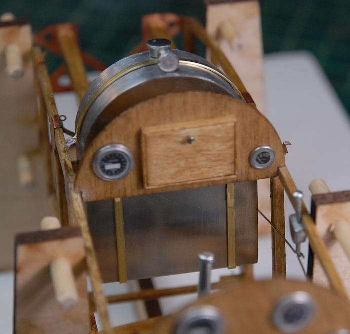
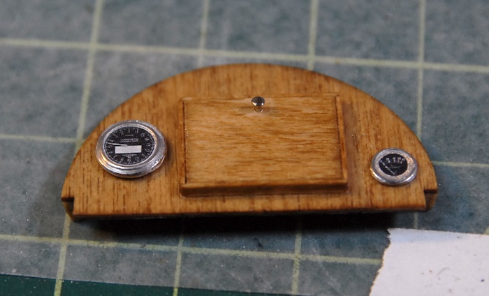
Here are the two control panels. The front one (for the navigator) has a little scratch-built map case. Although it's a little blurry in this image, the knob for the map case door is made from a pin head. I've left the dials and such off, as I wanted to stain and polyurethane the parts first.
Here is the fuselage right after staining.
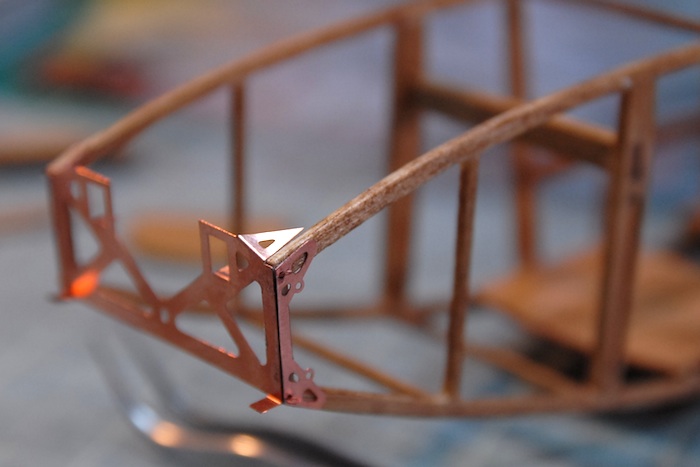
Once the stain and polyurethane were on there, I could start gluing on some of the photo-etch metal parts. Here is a close-up of the frame that goes in front of the engine.
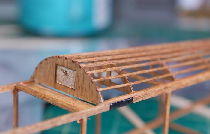
Here is a close-up of the little door that is at the front end of the turtleback.
Next up was something new to me: printing my own decals. The kit doesn't provide any sort of instrumentation graphics, but rather only comes with the cast metal base parts. I thought this might be a good excuse to try my hand at making decals. I picked up a package of ink-jet-printer decal sheets and a can of decal sealer at my local hobby shop and then spent a few hours scouring the internet for images of old airplane gauges. With some cleanup work in Photoshop, and a bit of experimentation with the printer, I was able to print myself a few sheets of gauges. The sheets below have so many because I wasn't sure how tough the decals would be, and fully expected to ruin a few before getting one to transfer correctly. I also printed one set on a clear sheet and one on a white sheet. It turned out that the decals held up great and the white-backed ones looked good, so I have lots of extra gauges now.
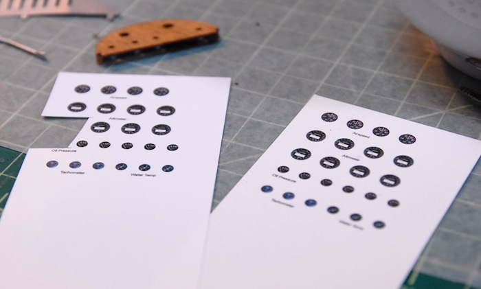
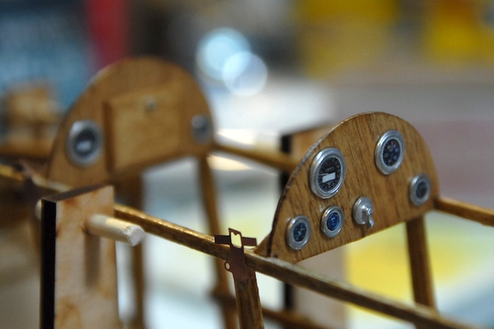
Here you can see a few of the gauge decals in place. Once all was said and done, I think they ended up a bit smaller than I would like, but I had erred on the small side to be sure that they would fit in the tiny embossed ring of the cast metal part.
Here are the two completed control panels in place and with all decals applied.
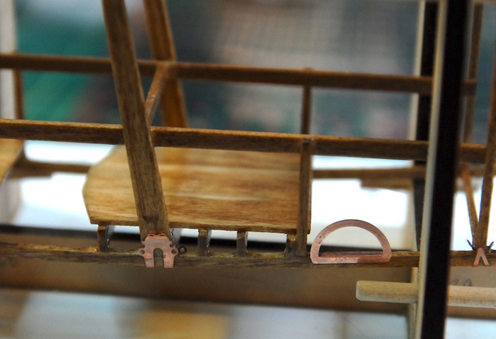
A few more photo-etched parts in place. The half-circle one is where the pilots step is, used to step up into the plane.
The engine-bearing supports, with various straps, wires, etc, holding them in place.
Finally, a sneak preview of the (in progress) next fun-filled step: Rigging the fuselage.
Thanks for tuning in! Hopefully next update will see the fuselage complete and work on the engine beginning.
With that in mind, here are some photos of what I've been up to, along with brief explanations.
Below is an image of the turtleback all assembled. It turns out that it would have probably been a better idea to assemble this off of the main fuselage, and then add it later, as it ended up making some of the rigging a bit harder.
Here is the whole fuselage right after having the turtleback attached and right before staining.
Here are the two control panels. The front one (for the navigator) has a little scratch-built map case. Although it's a little blurry in this image, the knob for the map case door is made from a pin head. I've left the dials and such off, as I wanted to stain and polyurethane the parts first.
Here is the fuselage right after staining.
Once the stain and polyurethane were on there, I could start gluing on some of the photo-etch metal parts. Here is a close-up of the frame that goes in front of the engine.
Here is a close-up of the little door that is at the front end of the turtleback.
Next up was something new to me: printing my own decals. The kit doesn't provide any sort of instrumentation graphics, but rather only comes with the cast metal base parts. I thought this might be a good excuse to try my hand at making decals. I picked up a package of ink-jet-printer decal sheets and a can of decal sealer at my local hobby shop and then spent a few hours scouring the internet for images of old airplane gauges. With some cleanup work in Photoshop, and a bit of experimentation with the printer, I was able to print myself a few sheets of gauges. The sheets below have so many because I wasn't sure how tough the decals would be, and fully expected to ruin a few before getting one to transfer correctly. I also printed one set on a clear sheet and one on a white sheet. It turned out that the decals held up great and the white-backed ones looked good, so I have lots of extra gauges now.
Here you can see a few of the gauge decals in place. Once all was said and done, I think they ended up a bit smaller than I would like, but I had erred on the small side to be sure that they would fit in the tiny embossed ring of the cast metal part.
Here are the two completed control panels in place and with all decals applied.
A few more photo-etched parts in place. The half-circle one is where the pilots step is, used to step up into the plane.
The engine-bearing supports, with various straps, wires, etc, holding them in place.
Finally, a sneak preview of the (in progress) next fun-filled step: Rigging the fuselage.
Thanks for tuning in! Hopefully next update will see the fuselage complete and work on the engine beginning.
Fuselage Continues
09 - May - 2011 - 20:27
In the last post, I mentioned that I was not happy with the construction method used in the kit instructions to make the mortised fuselage ribs. The instructions wanted the ribs to be cut from a solid piece and the mortises carved out from those. I made one test piece and found that: a) this is really hard b) the wood that the kit came with for these parts was not the best quality, and tended to flake apart during the carving and c) the final product, because of a and b, was simply not as refined and clean as I would like.
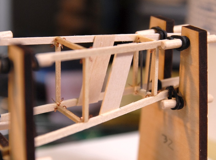
So, what I ended up doing was to get three strips of wood, cut the mortise shape out of two of them, and then sandwich them all together to create a much better looking part. Below you can see what I ended up with, as it is being glued to one half of the fuselage.
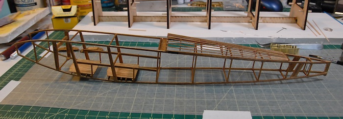
Once I got those parts all made, putting together the two sides of the fuselage went pretty quickly. Below you can see the two sides attached to the fuselage building jig, which holds everything straight and square while the cross pieces are glued in.
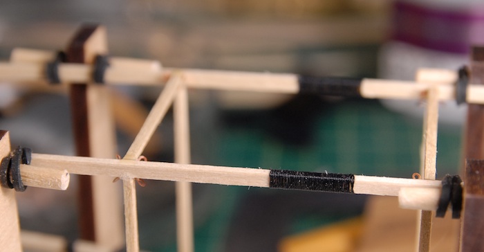
On the real plane, the top longerons (supposedly a real word) are spliced together behind the cockpit. I'm assuming this is because either a piece of wood that long was tricky to find, or perhaps the front of the plane needed wood of a different type that the tail did. Either way, my whole plane is made of basswood, and it's actually pretty easy to find a 16" long strip of wood, so I don't have to put in a real splice. Instead, the instructions had me wrap a section in thin nylon cord, to give the look of a spliced section.
At the tail of the fuselage, there are a number of additions that are meant to strengthen the structure around the tail skid. For my purposes, this just meant a couple thick strips on the sides and a few steel wires in between the top and bottom.
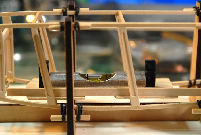
It was at this point that I found that I am going to need to start skipping sections of the instructions in order to facilitate the stain and polyurethane that I am putting on the model. I need to get as much of the wooden parts together, skip the addition of various metal parts, and still try to leave it all open enough that adding the metal parts later is easy. So, at this point I've skipped adding some of the engine mounting hardware because of the large photo-etch parts that that would require and have, instead, moved on to installing the cockpit flooring. Below you can see my efforts to get the two floors relatively level before fitting all the support beams underneath them.
Finally, here is the fuselage out of the building jig, and with the floor support beams in place. There is still lots of work to be done on the fuselage, but actually only a few more steps before I stain the whole thing and apply the polyurethane.
That's all I've got for now. Stay tuned for more action-packed model-building chronicles!!
So, what I ended up doing was to get three strips of wood, cut the mortise shape out of two of them, and then sandwich them all together to create a much better looking part. Below you can see what I ended up with, as it is being glued to one half of the fuselage.
Once I got those parts all made, putting together the two sides of the fuselage went pretty quickly. Below you can see the two sides attached to the fuselage building jig, which holds everything straight and square while the cross pieces are glued in.
On the real plane, the top longerons (supposedly a real word) are spliced together behind the cockpit. I'm assuming this is because either a piece of wood that long was tricky to find, or perhaps the front of the plane needed wood of a different type that the tail did. Either way, my whole plane is made of basswood, and it's actually pretty easy to find a 16" long strip of wood, so I don't have to put in a real splice. Instead, the instructions had me wrap a section in thin nylon cord, to give the look of a spliced section.
At the tail of the fuselage, there are a number of additions that are meant to strengthen the structure around the tail skid. For my purposes, this just meant a couple thick strips on the sides and a few steel wires in between the top and bottom.
It was at this point that I found that I am going to need to start skipping sections of the instructions in order to facilitate the stain and polyurethane that I am putting on the model. I need to get as much of the wooden parts together, skip the addition of various metal parts, and still try to leave it all open enough that adding the metal parts later is easy. So, at this point I've skipped adding some of the engine mounting hardware because of the large photo-etch parts that that would require and have, instead, moved on to installing the cockpit flooring. Below you can see my efforts to get the two floors relatively level before fitting all the support beams underneath them.
Finally, here is the fuselage out of the building jig, and with the floor support beams in place. There is still lots of work to be done on the fuselage, but actually only a few more steps before I stain the whole thing and apply the polyurethane.
That's all I've got for now. Stay tuned for more action-packed model-building chronicles!!
Tail Completion & Fuselage Start
24 - April - 2011 - 17:22
Lots of pictures and not much typing on this post. Enjoy the show!
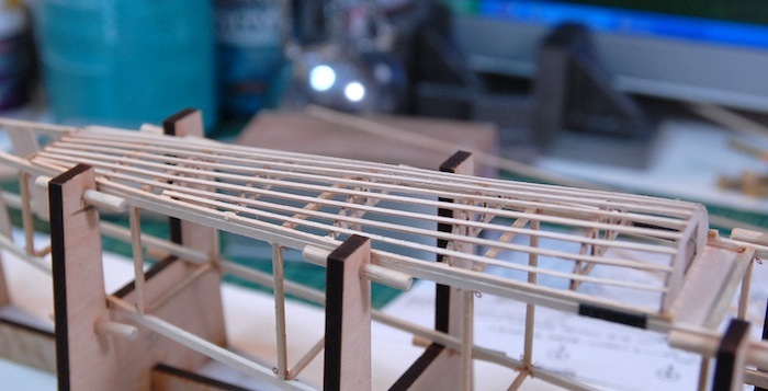
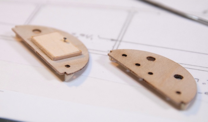
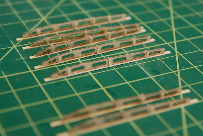
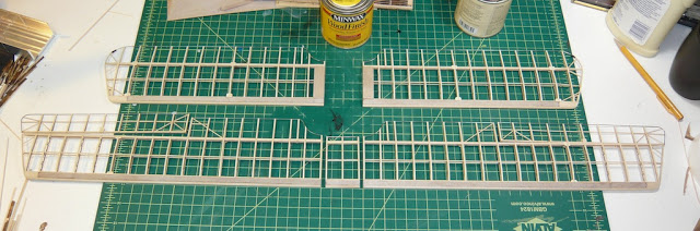
With the vertical stabilizer and rudder complete, I moved on to the horizontal stabilizer and elevator. The construction on this was very similar to that of the wings in that it is mostly laser-cut ribs and strip wood for strengthening and connecting. Here you can see the ribs with the lower cap strip and strengthening strips:
Here you can see the horizontal stabilizer going together on the plans sheet.
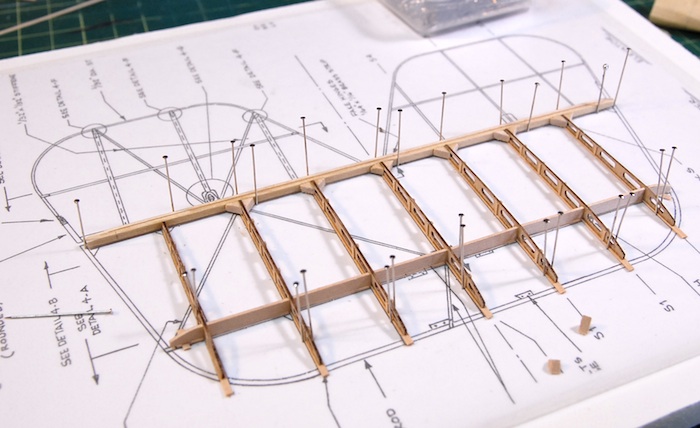
The leading edge on this piece is a steel rod, bent into shape after being heated up. The diagonal ribs are just strip wood cut and sanded into shape.
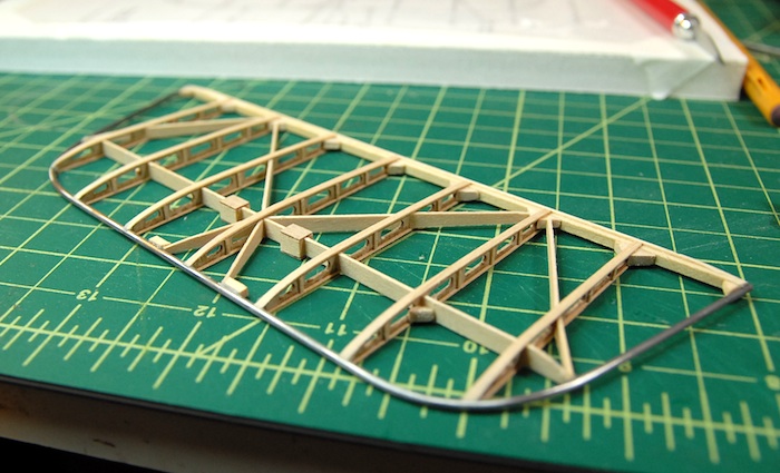
Once completed, this part can then be attached to the vertical stabilizer. Here you can see the connected pair drying after being stained.
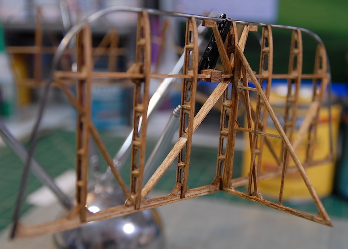
Once the stain and polyurethane was on the parts, I added the little bits of copper tape, which are meant to simulate the metal bands that hold the leading edge to the ribs.
With that completed, the hinge slots were cut and the brass strips were cut for the fake hinges. Below you can see the elevators attached and the tiny fake hinges in place.
Before setting these parts aside, I did a little bit of rigging on the elevators and rudder, so that they are all ready to attach to the fuselage later on in the build.
With these parts done (for now), I was ready to move on to the next major step in the build...
The Fuselage!!
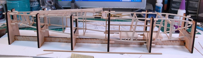
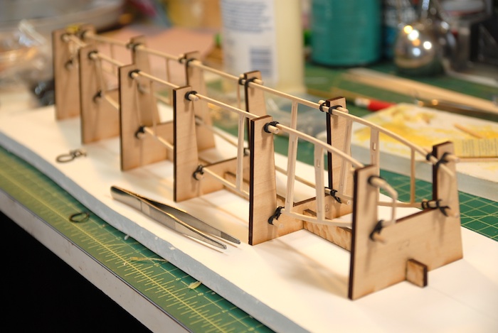
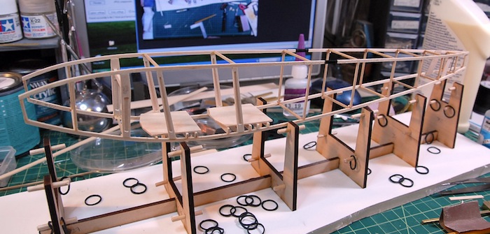
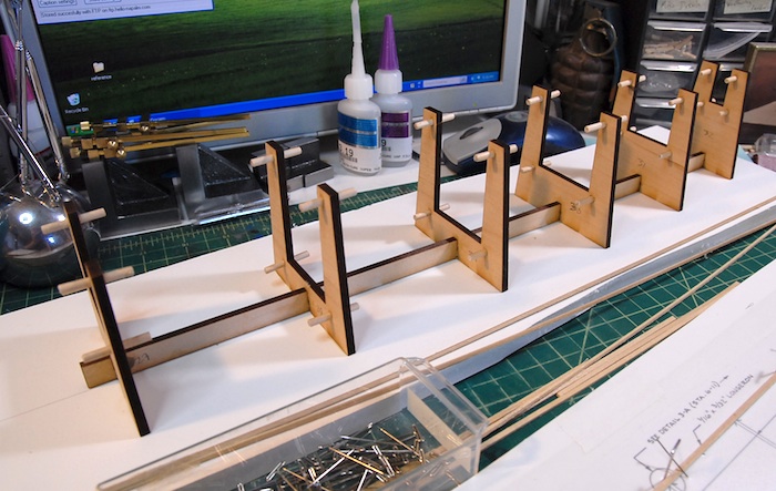
First and foremost, I had to put together a jig that will allow me to construct the fuselage in a square and true manner. The fit comes with a bunch of laser-cut parts that go together to form this jig, and below you can see it coming together.
The little dowels are so that the fuselage pieces can be attached with rubber bands later on. Also, the jig is glued down to that piece of foam board, so that it stays nice and straight through the process.
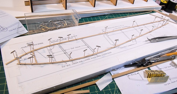
And finally, I've just soaked and bent the long pieces for one side of the fuselage frame. Here you can see it pinned down to the plans, with a few of the frame bits glued in (on the left side).
I've found that I'm not happy with the construction method for the three middle ribs. The pieces are supposed to have a mortise cut into each side of the rib, which is itself 1/16" thick. I've found that it is quite difficult to do this in a manner that doesn't look terrible. The wood tends to flake apart, or just look sloppy when I try to cut such a small amount out of it. Rather than keep trying or just settling for either non-mortised parts or sloppy-looking parts, I've decided to get some strips of very thin wood and attempt to build a sandwich-style rib, since I think cutting holes in thin wood will end up looking better than the carved-mortise version. I should end up with a part that looks just like it was carved out, except much cleaner and with much less hassle.
Tune in next time to see if my plan works ;)
With the vertical stabilizer and rudder complete, I moved on to the horizontal stabilizer and elevator. The construction on this was very similar to that of the wings in that it is mostly laser-cut ribs and strip wood for strengthening and connecting. Here you can see the ribs with the lower cap strip and strengthening strips:
Here you can see the horizontal stabilizer going together on the plans sheet.
The leading edge on this piece is a steel rod, bent into shape after being heated up. The diagonal ribs are just strip wood cut and sanded into shape.
Once completed, this part can then be attached to the vertical stabilizer. Here you can see the connected pair drying after being stained.
Once the stain and polyurethane was on the parts, I added the little bits of copper tape, which are meant to simulate the metal bands that hold the leading edge to the ribs.
With that completed, the hinge slots were cut and the brass strips were cut for the fake hinges. Below you can see the elevators attached and the tiny fake hinges in place.
Before setting these parts aside, I did a little bit of rigging on the elevators and rudder, so that they are all ready to attach to the fuselage later on in the build.
With these parts done (for now), I was ready to move on to the next major step in the build...
The Fuselage!!
First and foremost, I had to put together a jig that will allow me to construct the fuselage in a square and true manner. The fit comes with a bunch of laser-cut parts that go together to form this jig, and below you can see it coming together.
The little dowels are so that the fuselage pieces can be attached with rubber bands later on. Also, the jig is glued down to that piece of foam board, so that it stays nice and straight through the process.
And finally, I've just soaked and bent the long pieces for one side of the fuselage frame. Here you can see it pinned down to the plans, with a few of the frame bits glued in (on the left side).
I've found that I'm not happy with the construction method for the three middle ribs. The pieces are supposed to have a mortise cut into each side of the rib, which is itself 1/16" thick. I've found that it is quite difficult to do this in a manner that doesn't look terrible. The wood tends to flake apart, or just look sloppy when I try to cut such a small amount out of it. Rather than keep trying or just settling for either non-mortised parts or sloppy-looking parts, I've decided to get some strips of very thin wood and attempt to build a sandwich-style rib, since I think cutting holes in thin wood will end up looking better than the carved-mortise version. I should end up with a part that looks just like it was carved out, except much cleaner and with much less hassle.
Tune in next time to see if my plan works ;)
Wing Skids and Tail Parts
27 - March - 2011 - 20:07
As the building continues, I've finally completed all the little details on the wings. There were lots of little metal fittings, bits of rigging, and wooden supports that go along with the wings that all needed to be built before I moved on. For example, you can see below, the supports that go between the upper and lower wings. These were made from laser cut basswood with cast metal fittings on each end. Unfortunately, the notches that the cast metal fit into were not laser cut into the parts, so these took quite a bit of carving, sanding and filing in order to shape the wooden parts correctly. Once the metal parts were fitted, then the wooden middle needed to be sanded round and the metal ends polished to a shine.
In this image, the parts are drying after having been stained to match the rest of the model.
Similarly, the below part is the support that goes between the upper center wing section and the top of the fuselage. A similar carving/sanding/filing technique was required on these in order to get the metal end fittings integrated.
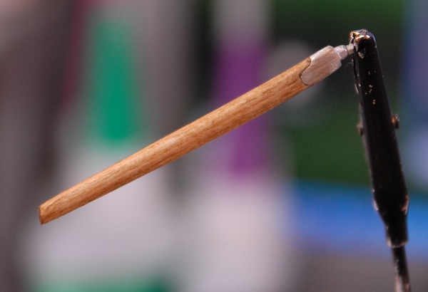
Also on the list of odds and ends were the skids that go on the bottom of the lower wings. On the real plane these were installed to help prevent catching a wing tip on a messy landing. On the model, they are made from a bent piece of wood. Since this bend was somewhat extreme, given that it was a 1/16" x 1/16" piece of wood, I decided to try a few new techniques for prepping the wood for bending. I tried wrapping it in a wet paper towel and then microwaving that, but didn't really have any luck there. Finally I just settled on good old fashioned soaking of the wood for an hour or so each. Below you can see the wood parts pinned down to the plans as they dry.
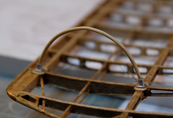
And here are the skids installed on the bottom of the wing, prior to stain and polyurethane.
That pretty much wrapped up the miscellaneous wing parts (there were a few others, like the king posts on the upper wings, but I don't have photos of those), so I finally got to move along to some non-wing parts.
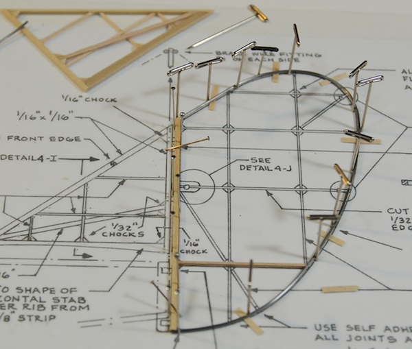
First on the list are the tail surfaces. I started with the vertical stabilizer and rudder. The vertical stabilizer was a quick build, since it was just strip wood, pinned over the plan and glued in place. The rudder was a little more complicated, but still fairly simple. Like the wings, the rudder has a trailing edge made of bent wire. I used the same technique as I had previously to make the wire easier to work with. This involved annealing the wire, using a cooking torch (like for making creme brulee) to get the wire red hot and then let it cool back down again. This makes it a bit softer after it cools and easier to work with.
Below you can see the bent wire pinned in place and shimmed off the plans just a bit (so that it is centered to the leading edge) with the first of the ribs glued in place.
I've just finished the rudder, which was also pretty much just simple strip wood, cut, sanded and glued in place. Below you can see the completed parts. They still need to be stained, polyurethaned and then fitted with a few metal parts, but that'll come later, once the elevator is done. I've got to wait until the elevator is done because the bottom of the vertical stabilizer needs to be sanded to fit the top of the elevator so they both need to be complete before I can do the final fitting and then stain, etc.
The finished parts:
In this image, the parts are drying after having been stained to match the rest of the model.
Similarly, the below part is the support that goes between the upper center wing section and the top of the fuselage. A similar carving/sanding/filing technique was required on these in order to get the metal end fittings integrated.
Also on the list of odds and ends were the skids that go on the bottom of the lower wings. On the real plane these were installed to help prevent catching a wing tip on a messy landing. On the model, they are made from a bent piece of wood. Since this bend was somewhat extreme, given that it was a 1/16" x 1/16" piece of wood, I decided to try a few new techniques for prepping the wood for bending. I tried wrapping it in a wet paper towel and then microwaving that, but didn't really have any luck there. Finally I just settled on good old fashioned soaking of the wood for an hour or so each. Below you can see the wood parts pinned down to the plans as they dry.
And here are the skids installed on the bottom of the wing, prior to stain and polyurethane.
That pretty much wrapped up the miscellaneous wing parts (there were a few others, like the king posts on the upper wings, but I don't have photos of those), so I finally got to move along to some non-wing parts.
First on the list are the tail surfaces. I started with the vertical stabilizer and rudder. The vertical stabilizer was a quick build, since it was just strip wood, pinned over the plan and glued in place. The rudder was a little more complicated, but still fairly simple. Like the wings, the rudder has a trailing edge made of bent wire. I used the same technique as I had previously to make the wire easier to work with. This involved annealing the wire, using a cooking torch (like for making creme brulee) to get the wire red hot and then let it cool back down again. This makes it a bit softer after it cools and easier to work with.
Below you can see the bent wire pinned in place and shimmed off the plans just a bit (so that it is centered to the leading edge) with the first of the ribs glued in place.
I've just finished the rudder, which was also pretty much just simple strip wood, cut, sanded and glued in place. Below you can see the completed parts. They still need to be stained, polyurethaned and then fitted with a few metal parts, but that'll come later, once the elevator is done. I've got to wait until the elevator is done because the bottom of the vertical stabilizer needs to be sanded to fit the top of the elevator so they both need to be complete before I can do the final fitting and then stain, etc.
The finished parts:
And One Month Later....
13 - March - 2011 - 19:52
The wings are all rigged and nearly complete!
After a few weeks of tying tiny little copper fitting to short lengths of string, I managed to tie at least a few on to the model itself. I managed to come up with a fairly successful system where I tied all of the string to the little copper turnbuckles first and then tied them to the wing itself. I originally was doing one string at a time, tying the turnbuckle to the string and then the string to the model, but found this to be pretty slow going.
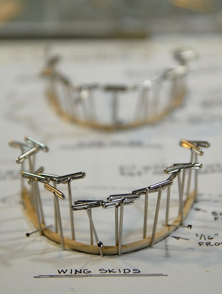
Here you can see a bunch of the pre-tied turnbuckles ready to go onto the lower wing panels. I have found that some of my ship-modeling skills have been helpful when it comes to knots and such.
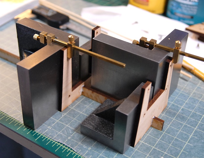
Once I had all of the rigging in the wings complete, then it was time to add various other copper and white metal fittings. This gave me the opportunity to use a new toy I purchased at the beginning of this project. It is a 'Hold and Fold' photo-etch workstation from the nice folks at The Small Shop. As you can see in the photo, it is a billet aluminum clamp-like device that let's me clamp a bit of photo-etched metal down (very precisely) and then fold it using that great big razor blade. I got to use it a bit today to crease some of the rigging plate things that go on to the wings and will eventually be clamped between the wing and the posts that connect the two wings.
Once I had all of the rigging in the wings complete, then it was time to add various other copper and white metal fittings. This gave me the opportunity to use a new toy I purchased at the beginning of this project. It is a 'Hold and Fold' photo-etch workstation from the nice folks at The Small Shop. As you can see in the photo, it is a billet aluminum clamp-like device that let's me clamp a bit of photo-etched metal down (very precisely) and then fold it using that great big razor blade. I got to use it a bit today to crease some of the rigging plate things that go on to the wings and will eventually be clamped between the wing and the posts that connect the two wings.
I also spent a bit of time filing, sanding and polishing a few cast white metal parts which were put together to become the little pulleys that control the ailerons. I've still got two more to add, but here are the tops ones in place:
That's all for now! With the wings nearly complete, I'll soon be moving on to the tail parts. Until next time.
After a few weeks of tying tiny little copper fitting to short lengths of string, I managed to tie at least a few on to the model itself. I managed to come up with a fairly successful system where I tied all of the string to the little copper turnbuckles first and then tied them to the wing itself. I originally was doing one string at a time, tying the turnbuckle to the string and then the string to the model, but found this to be pretty slow going.
Here you can see a bunch of the pre-tied turnbuckles ready to go onto the lower wing panels. I have found that some of my ship-modeling skills have been helpful when it comes to knots and such.
Once I had all of the rigging in the wings complete, then it was time to add various other copper and white metal fittings. This gave me the opportunity to use a new toy I purchased at the beginning of this project. It is a 'Hold and Fold' photo-etch workstation from the nice folks at The Small Shop. As you can see in the photo, it is a billet aluminum clamp-like device that let's me clamp a bit of photo-etched metal down (very precisely) and then fold it using that great big razor blade. I got to use it a bit today to crease some of the rigging plate things that go on to the wings and will eventually be clamped between the wing and the posts that connect the two wings.
Once I had all of the rigging in the wings complete, then it was time to add various other copper and white metal fittings. This gave me the opportunity to use a new toy I purchased at the beginning of this project. It is a 'Hold and Fold' photo-etch workstation from the nice folks at The Small Shop. As you can see in the photo, it is a billet aluminum clamp-like device that let's me clamp a bit of photo-etched metal down (very precisely) and then fold it using that great big razor blade. I got to use it a bit today to crease some of the rigging plate things that go on to the wings and will eventually be clamped between the wing and the posts that connect the two wings.
I also spent a bit of time filing, sanding and polishing a few cast white metal parts which were put together to become the little pulleys that control the ailerons. I've still got two more to add, but here are the tops ones in place:
That's all for now! With the wings nearly complete, I'll soon be moving on to the tail parts. Until next time.
Wing Staining & Rigging
12 - February - 2011 - 17:12
Work on the wings continues...
Since the last post, I've finished the staining of the wing panels and then put a few coats of a semi-gloss water-based polyurethane. This is to seal up the wood as well as to add some depth to the finish. Overall, I am pretty happy with the way the finish turned out and it makes a fantastic contract to the white metal and copper parts. Here is an image of one of the stained and finished lower wing panels:
It did take quite a while to get the stain and poly on there, since it all had to be brushed on by hand. I feel that the results were worth it, though.
The next step in the process was to add the adhesive copper tape strips to the ends of the ribs at the trailing edge. These are to simulate the bands of metal that clamped on the trailing edge on the real plane. This was pretty easy, since the copper tape is very malleable, and can be smoothed down with a fingernail and the edges burnished smooth with some tweezers.
Here is a photo of the aileron edge with tape applied. I really like the way the copper looks against the stained wood.
Next, I pulled out a few of the white metal parts and had a go at polishing them up a bit. They come with a fairly matte finish and with some imperfections in the casting. I bit of work with various sanding sticks and they shine up nicely. Here you can see the aileron control horns attached to the ailerons, and also the fake hinges (made of strip brass) sticking off of the back of the parts.
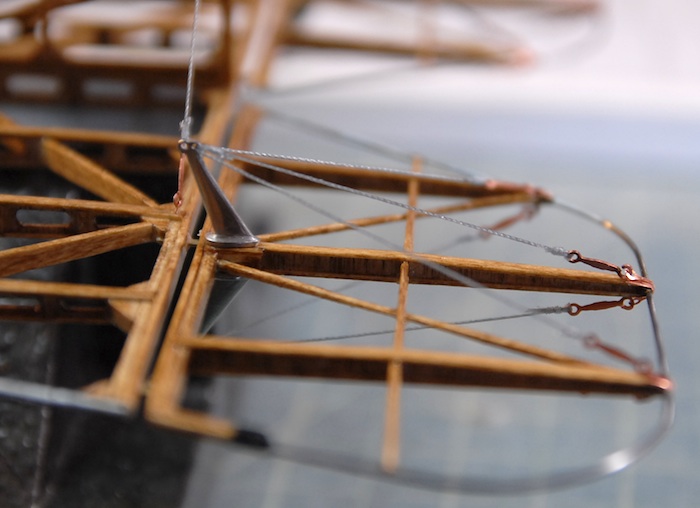
Now, I am on to the rigging step, where all the turnbuckles and wires that maintain the internal wing structure are put into place. I'm finding that some of my experience on the Armed Virginia Sloop model is coming in handy, in that I can reuse some of the rigging techniques that I learned on that project. Here is a pic of the first part that has been completed:
This rigging stuff, while not too complicated, is a bit fiddly and generally slow-going. I'm expecting that I'll probably spend the next couple of weeks on this, and will have another update once that is complete. Stay tuned until then!
Since the last post, I've finished the staining of the wing panels and then put a few coats of a semi-gloss water-based polyurethane. This is to seal up the wood as well as to add some depth to the finish. Overall, I am pretty happy with the way the finish turned out and it makes a fantastic contract to the white metal and copper parts. Here is an image of one of the stained and finished lower wing panels:
It did take quite a while to get the stain and poly on there, since it all had to be brushed on by hand. I feel that the results were worth it, though.
The next step in the process was to add the adhesive copper tape strips to the ends of the ribs at the trailing edge. These are to simulate the bands of metal that clamped on the trailing edge on the real plane. This was pretty easy, since the copper tape is very malleable, and can be smoothed down with a fingernail and the edges burnished smooth with some tweezers.
Here is a photo of the aileron edge with tape applied. I really like the way the copper looks against the stained wood.
Next, I pulled out a few of the white metal parts and had a go at polishing them up a bit. They come with a fairly matte finish and with some imperfections in the casting. I bit of work with various sanding sticks and they shine up nicely. Here you can see the aileron control horns attached to the ailerons, and also the fake hinges (made of strip brass) sticking off of the back of the parts.
Now, I am on to the rigging step, where all the turnbuckles and wires that maintain the internal wing structure are put into place. I'm finding that some of my experience on the Armed Virginia Sloop model is coming in handy, in that I can reuse some of the rigging techniques that I learned on that project. Here is a pic of the first part that has been completed:
This rigging stuff, while not too complicated, is a bit fiddly and generally slow-going. I'm expecting that I'll probably spend the next couple of weeks on this, and will have another update once that is complete. Stay tuned until then!
Wings Done!
30 - January - 2011 - 20:06
Another long lost update to the blog! Although this time I have a better excuse. I haven't updated before now because everything that I have been doing in between this and the last post has been pretty boring. Not that it's been boring to work on, per se, but rather it's almost the exact same tasks I've already blogged about, just more so. So rather than post about how I've sanded ANOTHER 40 ribs, I figured I'd just wait until there was something more interesting to see.
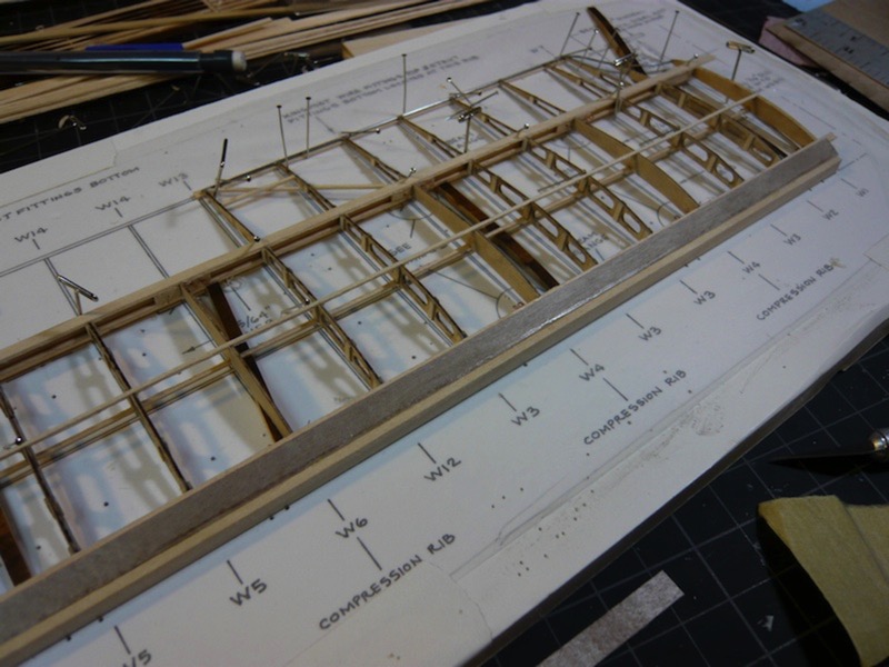
I've finally finished the main construction on the four wing panels. This includes most all of the wooden parts, and just a few metal bits. The only metal parts that are on there at the moment are either structural (like the trailing edge wire) or would be too tricky to install later in the construction process (like the little eyelets in the middle areas). So with that taken care of, I can finally apply the stain and polyurethane to the wings in preparation for further construction. Below you can see the completed wing panels.
Once the stain and poly are applied, I'll be able to rig the internal wires on the wings and apply various other braces and supports. Here is a snapshot of the wing panels hung up to dry after being stained.
Stay tuned for more action-packed adventure!
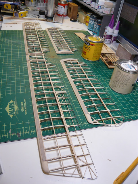
I've finally finished the main construction on the four wing panels. This includes most all of the wooden parts, and just a few metal bits. The only metal parts that are on there at the moment are either structural (like the trailing edge wire) or would be too tricky to install later in the construction process (like the little eyelets in the middle areas). So with that taken care of, I can finally apply the stain and polyurethane to the wings in preparation for further construction. Below you can see the completed wing panels.
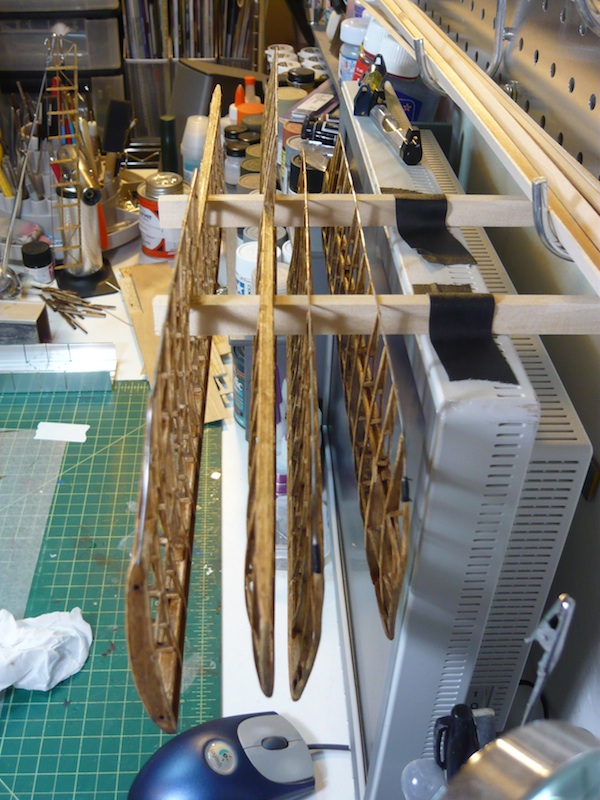
Once the stain and poly are applied, I'll be able to rig the internal wires on the wings and apply various other braces and supports. Here is a snapshot of the wing panels hung up to dry after being stained.
Stay tuned for more action-packed adventure!
Long Lost Update...
09 - November - 2010 - 21:15
At long last, I'm updating the blog again. In the interim, I spent a week in Hawaii, played through Fallout: New Vegas, and have just been busy with life in general. But last weekend, I finally got back to working on the model again. Here is where things stand thus far...
I've finished the wood work on one of the upper wing panels. This includes both the wing panel and the aileron. While the panal isn't DONE yet, it's reached the point that I'll need to stain and seal it, so I decided it would probably be best if I built all the wing panels and THEN did the staining and sealing. Once that is done, there are a variety of metal and string parts that go on the wings as well.
As you can see in the various photos here, I'm making slow but steady progress.
Starting on the next wing panel, I'm taking a bit from what I learned from the first and making sure I have much of the sanding and fitting done beforehand. This means that I've got to do all the monotonous filing first, but it should make assembly go much faster overall.
Here is a photo of a before and after wing rib. You can see how I'm also sanding off the blackening on the edges of the cutouts. This blackening is from the laser cutting of the parts, and I feel that removing it will add a bit to the scale fidelity of the model. The drawback is that it's a royal pain in the butt, and some of these wing ribs are pretty fragile and are easily broken while sanding. Hooray for super glue!
Stay tuned for further adventures in modeling!
Curtis Jenny Progress
11 - September - 2010 - 08:05
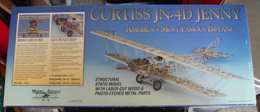
Here is a little update on what I've been up to. I've started a new project. This time it is a wooden/metal kit instead of plastic. It is a World War I era biplane, and will end up as a static display (non flying) model with all the internal details visible.

This one is both similar and quite different from the wooden ship that I previously built. This project has generally the same raw materials: laser-cut wood, stock strip wood, cast white metal, etc. The big difference this time around is that I'm not following a course on the projects construction. This just means that I have to follow the somewhat rough instructions that come with the model itself and do much more deciphering of the sheet plans. This isn't a bad thing, just a different challenge.
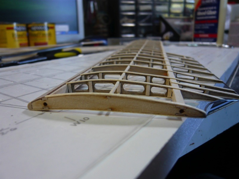
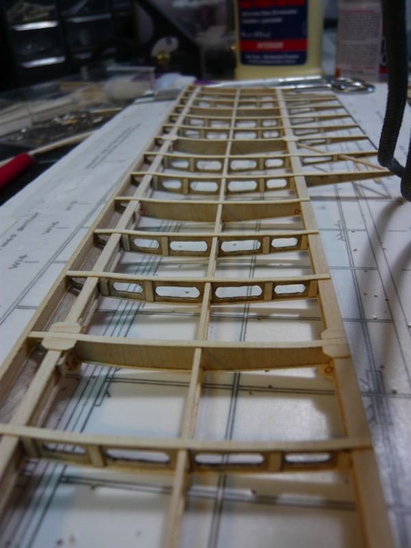
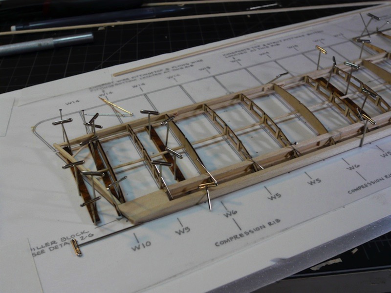
So, I've decided to start with one of the top wing panels, in order to go through most of it's construction, and learn what I can in the process. In theory, this should confine all my screw-ups to just one wing panel, making for less fixing later and smoother/faster construction of the other three panels. With that said, here are some photos of my progress thus far:
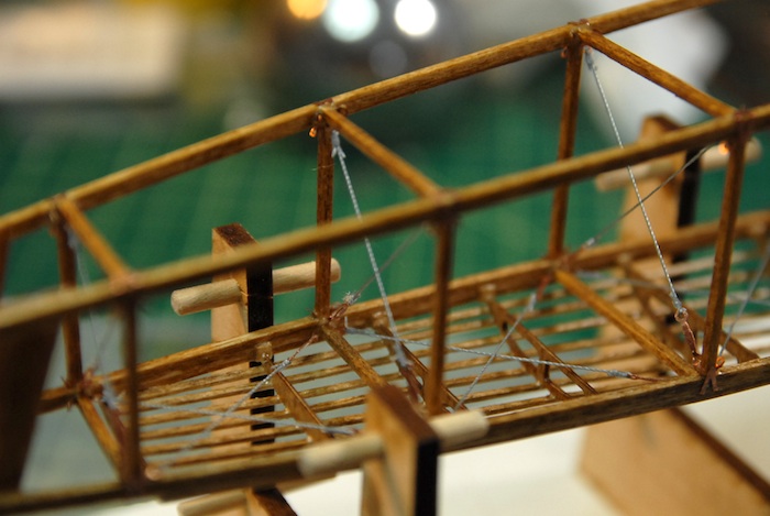
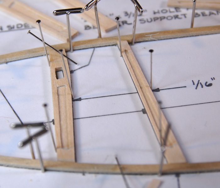
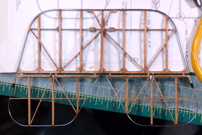
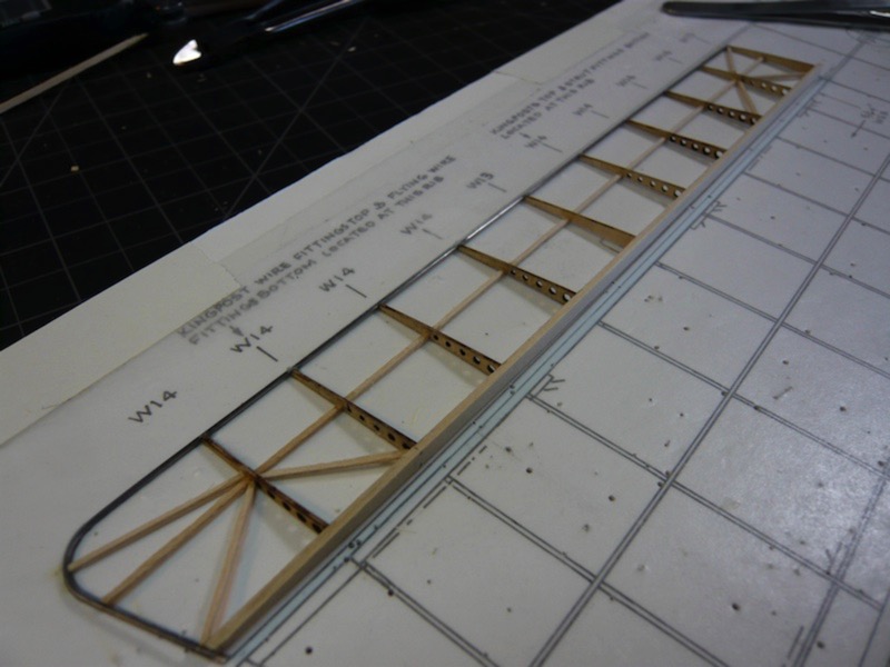
Initial wing ribs layout.
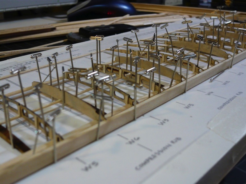
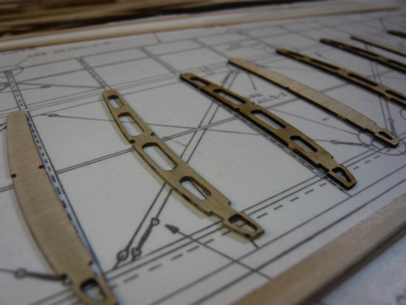
Photo-etched fittings for later wire rigging.
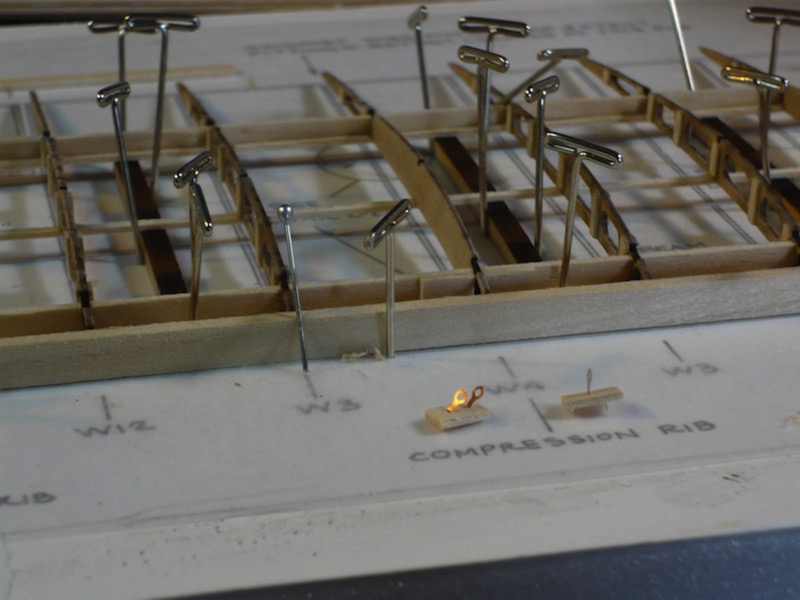
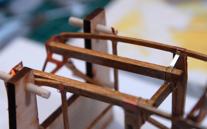
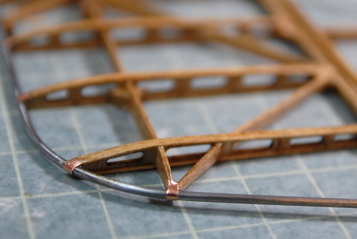
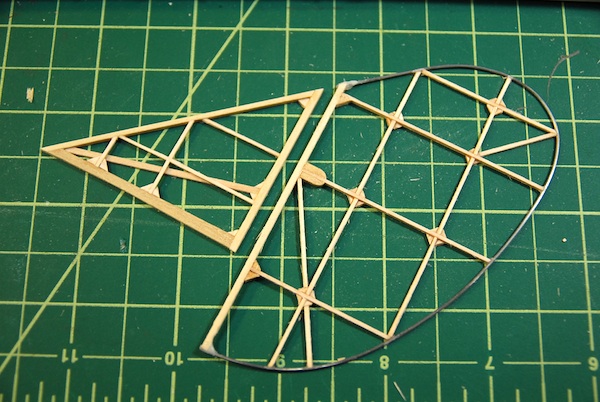
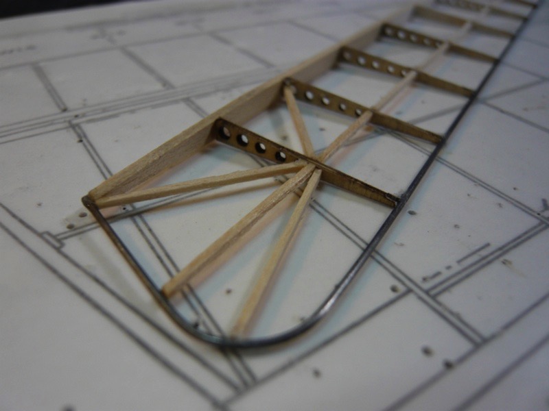
Bending the wing tip rib.
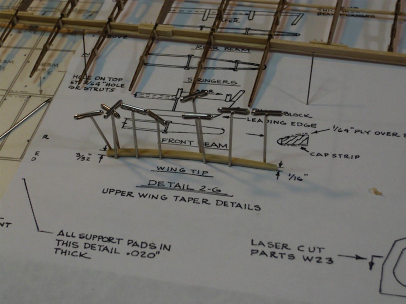
More wing tip construction.
With the thin plywood leading edge cap strip.
Progress has been a bit slow so far, as I've not had as much free time as I would like. But, stay tuned for more progress, some wood stain color tests and further adventures in modeling!
This one is both similar and quite different from the wooden ship that I previously built. This project has generally the same raw materials: laser-cut wood, stock strip wood, cast white metal, etc. The big difference this time around is that I'm not following a course on the projects construction. This just means that I have to follow the somewhat rough instructions that come with the model itself and do much more deciphering of the sheet plans. This isn't a bad thing, just a different challenge.
So, I've decided to start with one of the top wing panels, in order to go through most of it's construction, and learn what I can in the process. In theory, this should confine all my screw-ups to just one wing panel, making for less fixing later and smoother/faster construction of the other three panels. With that said, here are some photos of my progress thus far:
Initial wing ribs layout.
Photo-etched fittings for later wire rigging.
Bending the wing tip rib.
More wing tip construction.
With the thin plywood leading edge cap strip.
Progress has been a bit slow so far, as I've not had as much free time as I would like. But, stay tuned for more progress, some wood stain color tests and further adventures in modeling!
A Sneak Preview
19 - June - 2010 - 08:22
Just a quick post to bring things up to date. Here's a quick look at upcoming projects.
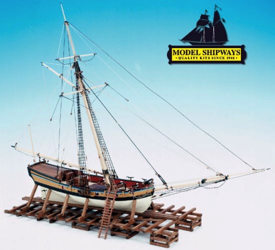
This past week I received a kit for another wooden and metal model. This one is a WWI biplane, the Curtiss JN-4D 'Jenny'. I'm hoping that it'll be a challenging build, similar to the Sloop build, except with much more metal and photo-etch. I'm actually hoping to set up a time-lapse recording method for this build, using an old computer, and a webcam. But since I think this might take me a little bit to get set up and tested, I'm going to hold off on starting this build for a little while.

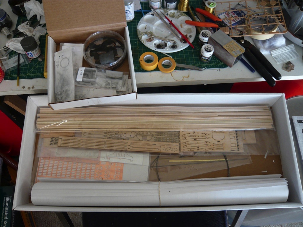
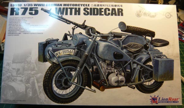
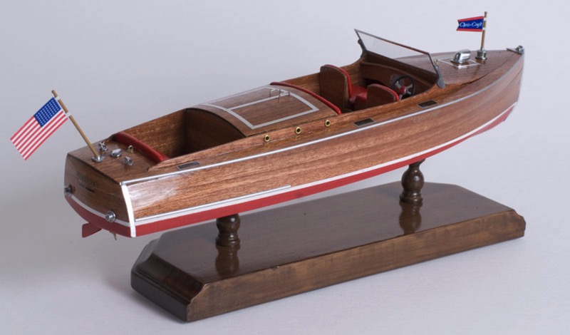
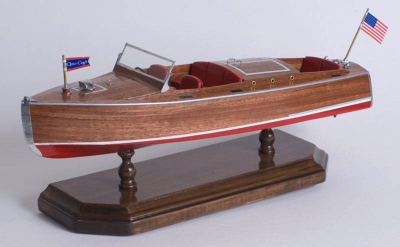
So, in the meantime, after wrapping up the motorcycle model (which I plan on doing today), I'll be putting this one together:
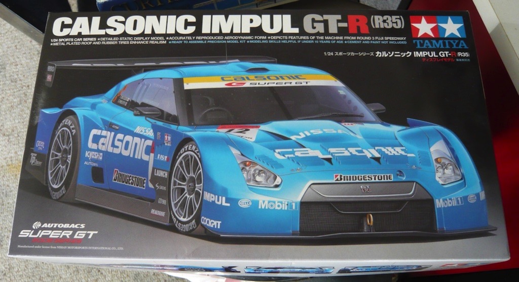
It should be a quick, fun build, since there isn't any engine. I was in the mood to make something shiny before I start on a longer build, so I figure I can crank through this one in a few weeks, and should be able to test out my time-lapse setup in the process :)
And there we have it. That's my modeling progress brought up to date. Party on.
This past week I received a kit for another wooden and metal model. This one is a WWI biplane, the Curtiss JN-4D 'Jenny'. I'm hoping that it'll be a challenging build, similar to the Sloop build, except with much more metal and photo-etch. I'm actually hoping to set up a time-lapse recording method for this build, using an old computer, and a webcam. But since I think this might take me a little bit to get set up and tested, I'm going to hold off on starting this build for a little while.
So, in the meantime, after wrapping up the motorcycle model (which I plan on doing today), I'll be putting this one together:
It should be a quick, fun build, since there isn't any engine. I was in the mood to make something shiny before I start on a longer build, so I figure I can crank through this one in a few weeks, and should be able to test out my time-lapse setup in the process :)
And there we have it. That's my modeling progress brought up to date. Party on.