
Resin
Inc in Grey Gallery
15 - May - 2016 - 20:13
As a follow-up to the last blog entry, I’ve put together a gallery of the finished Inc model.
Because of the tight timeline on which I put this one together (in order to make book publishing deadlines), I don’t have any photos of the in-progress build. Fortunately, I’ve still got another kit worth of parts AND the molds to make more parts. So, keep an eye out for future blog posts when I do get back around to making another of this model. Perhaps I’ll even paint that one!
You can find the gallery here, or click the image below.
Thanks for reading!
Inc Project
04 - April - 2016 - 10:18
A little while back, I put the Ferrari Enzo project aside so that I could try something new.
A good friend of mine, Neil Blevins, along with Bill Zahn, Stephan Bugaj, and a collection of concept art all-stars, have been working on an ‘art of’ book of sorts. For those unfamiliar, an ‘art of’ book is usually a book that contains the concept art for a film, television series, or something similar, i.e. ‘The Art of Inside Out’ or ‘The Art of Game of Thrones.’ The big difference here is that this book is full of art for a production that has not yet been made. They’ve been painting images and writing a story for a few years and this presented an opportunity for me to add my own bit of flavor to the mix.
I’d been interested in trying my hand at producing a garage resin model kit for a while, so that I could learn a bit more about the process. I talked to Neil about such a project and we decided that I would take his digital 3d model of the main character, who is a can-shaped robot, and see if I could turn it into a model kit. This blog post is about some of that process.
First off, I received a 3d file from Neil, which was the version of the main character that he was using to digitally render images from. It was set up to look good in pictures, but had lots of fine detail and various features that would be tricky to turn into physical object. Neil and I had agreed that we’d like to aim for a completed model that was 8-10 inches tall, which meant roughly 1/18 scale for this character (it was meant to be a pretty large robot). So, it fell to me to take his digital 3d model and figure out how to shrink it down, alter it and cut it up so that it could both be 3d printed and then replicated in resin, and then actually print it, clean up the prints, make molds of the parts, make castings from those molds and finally put at least one kit together so that Neil could put images of it into the book that they were working on.
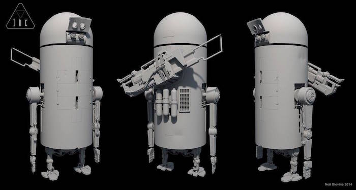
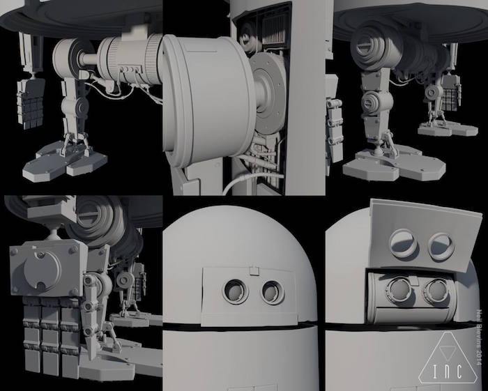
Here are a few views of the digital model that I was working from.
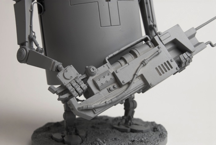
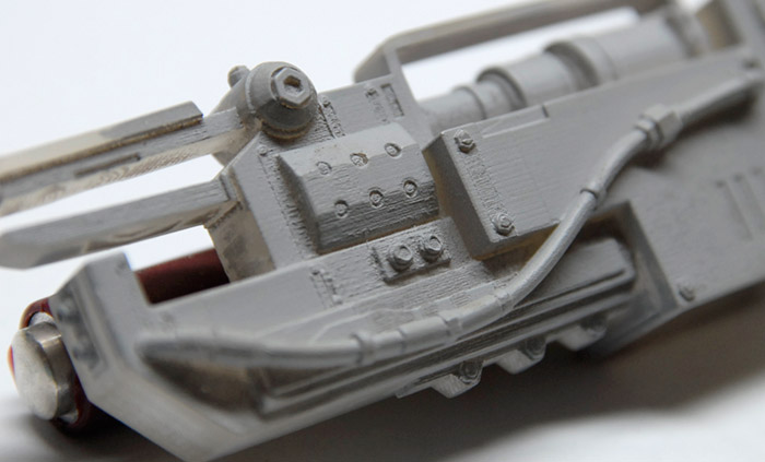
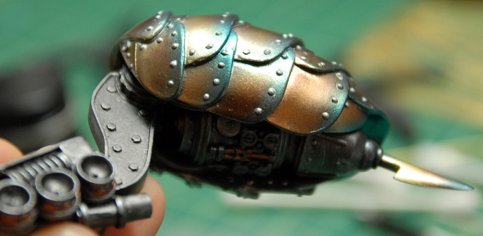
Before jumping into the bulk of the work, I did a bit of a test. The robot had a weapon of sorts that was part gun and part spot welder. It was a fairly complex shape, with both thick and thin areas and would make a decent trial for the printing, clean up and mold making. After a few additions in the 3d file, to bridge some gaps, add some support and make it a little more mold friendly (less undercuts), I had the gun printed at Shapeways. Below you can see the print I got back, sprayed with an initial coat of primer.
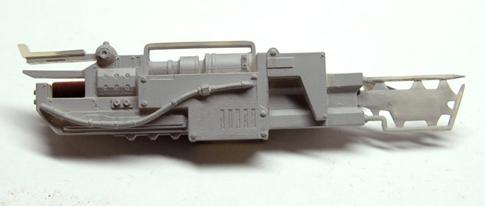
The print itself was a little rough in a few areas, so it required a few cycles of priming and sanding, in order to fill in and smooth out the striations that the printing left behind. Below you can see a close up of one such area and the ridges on the flat surfaces that should be smooth.
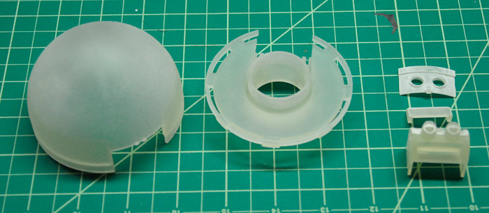
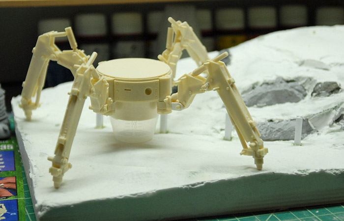
With that test done, and a few lessons learned (how to keep print costs down, basic mold pouring techniques learned, etc), I moved on to a few more pieces. Below you can see the head, split into three parts, as they arrived from the printer. They come in a clear plastic that makes it difficult to see the texture from the printing process. This is why I primed the parts before sanding, as otherwise it was nearly impossible to see if the surface was smooth or not.
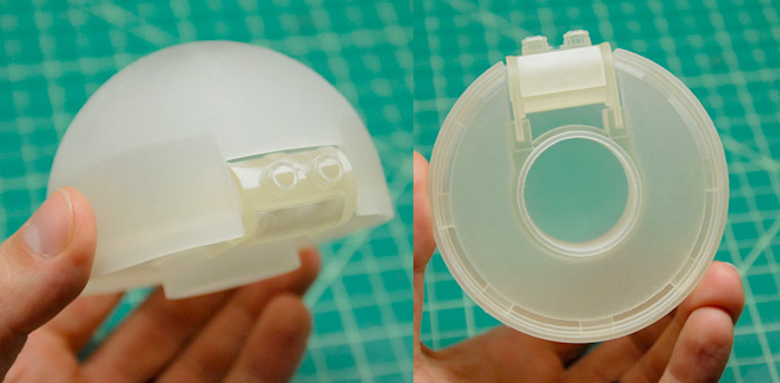
Here is how they go together, just press-fit in this photo:
Once the long and dull process of prepping all of the parts for mold making was complete, I split the mold making process into two main groups: single-piece molds and two-piece molds. The single-piece molds are for relatively flat parts, that only have detail on one side. The parts can be attached to a board, have a little box built around them and the silicon poured over them. The two-piece molds are for parts that have detail all around them. Those are more complicated to make molds for and require a form be built up around them with something like clay, defining where the mold seam will be. A pour spout and registration indentations need to be added so that the mold halves align and there is a place to pour in the resin in the finished mold.
First though, a bit about this process: Since the intent here is to make resin castings, using silicon rubber as the mold material, the requirements are a little different than if I were making molds for something like injection molded plastic kits. The silicon has a great deal of flexibility, so there can be some undercuts on the piece to be cast, and you don’t have to worry about the piece getting stuck in the mold. Also, basic molding and casting with these materials don’t strictly require any special equipment, although the addition of a few small machines can help the quality level a great deal.
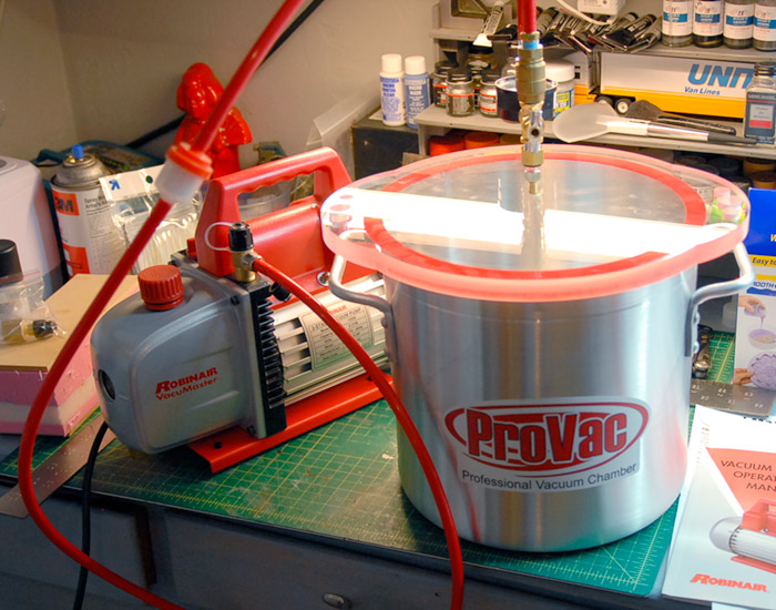
In my case, I opted to supplement my process with the addition of a vacuum pump, a vacuum chamber, a pressure vessel and air compressor. I’ll go into more detail on those a bit later.
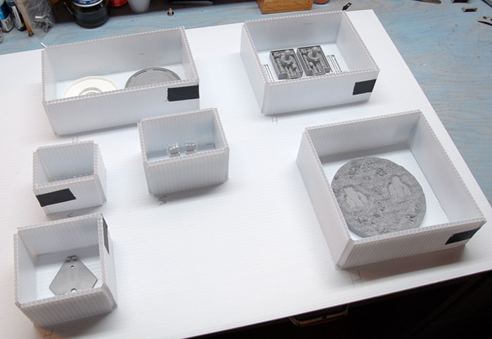
For the mold making, I started by ordering a box of corrugated plastic sheet. This stuff is commonly used for signs, but it is easy to cut, reasonably strong and inexpensive. For the one-part molds, I simply put a sheet down, hot-glued my parts to the sheet, and then built little walls around each part that would hold in the silicon. Those walls were hot-glued to the base and any gaps sealed up with more hot glue.
From what I had read, the mold should be at least 3/4” thick from the highest bit of the part being cast. I measured and marked on the walls of each box so I knew where to pour to. Now, when pouring a silicon mold, you’ll get the best mold quality if you eliminate bubbles from the silicon. Additionally, if you would like to pressure cast later on, you MUST get rid of the air bubbles in the silicon or they will give you a bumpy surface on your casting. There are a few ways to eliminate or minimize bubbles: pouring slowly into one corner of the mold (easy way, but not good for pressure casting), and vacuum degassing (harder, requires equipment, but good for pressure casting).
There is lots of information out there about mold making with silicon and casting with resin, so I’ll gloss over most of this. See the end of this post for links to various information sources to learn more.
The executive summary is that pouring your silicon from a little bit of a height (maybe 6 inches) and fairly slowly prevents bubbles from forming around your object, so you get good fidelity, but it does not prevent bubbles from forming in the silicon itself. So, if you are going to just pour resin into your mold and let it cure, this works just fine. If you are intending to pressure cast, you’ll need to get all the bubbles out of the silicon as well, so that requires another step: vacuum degassing. This is the technique of putting your mixed silicon under vacuum so that all the air bubbles expand and rise to the top, leaving your silicon bubble-free. If you skip this step, and pressure cast later, you’ll get what are commonly called ‘measles’ on the casting. These are when the bubbles in the silicon shrink under the pressure, and make little bumps on the casting, which you have to clean up later.
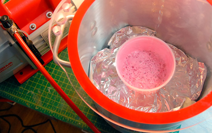
Since my goal was to be able to make the highest quality parts possible, I decided to invest in a bit of new equipment. This consisted of a vacuum chamber and a vacuum pump. This allows me to mix up a batch of silicon, put it into the vacuum chamber, place it under vacuum for a few minutes, watch all the air bubble out, and THEN pour it into my mold forms. Below you can see my setup and a batch of silicon bubbling away under vacuum.
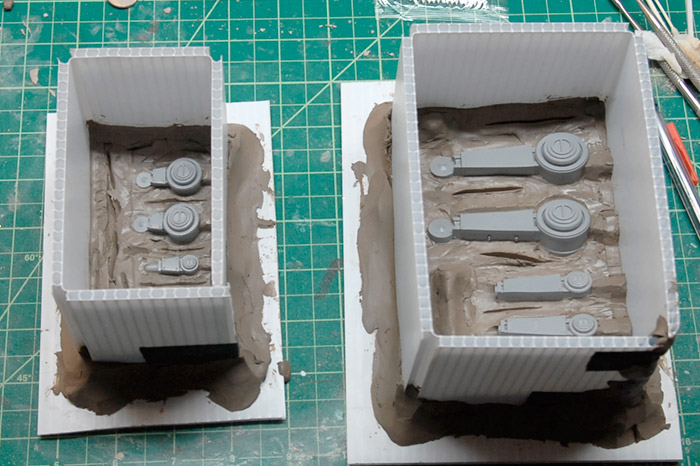
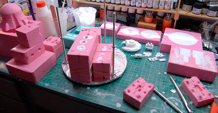
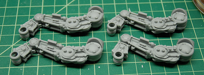
After the single-piece molds were poured and cured, and a test casting or two had been done, it was time to move on to the larger and more complex multi-piece molds. For these, I got a box of water-based clay to use to build up half of each mold. Below you can see the arms and legs in their molds, ready for the first part to be poured. You can see how there are a few divots and grooves to be used for registration as well as little lumps that will be the pour spouts at the top of each part. You can also see the final state of the 3d printed parts, after they had been sanded and primed a few times and then finally had a gloss clear coat sprayed onto them, in order to get a smoother finish on the cast parts.
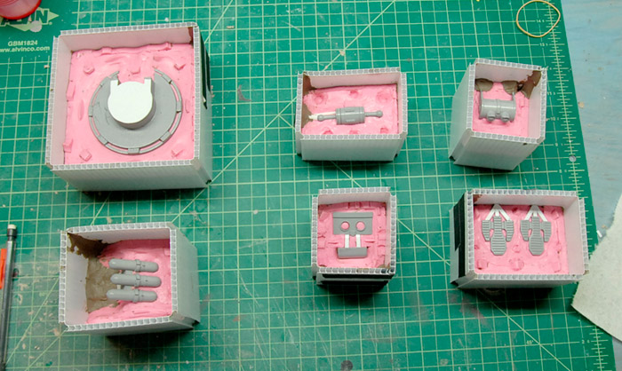
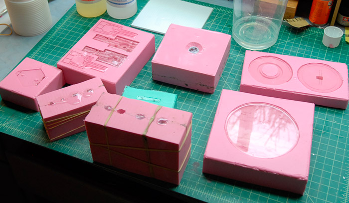
After pouring the first half, the molds are pulled off of their bases (but the sides left in place), the water-based clay washed away, some mold release agent sprayed on, and the other half of the mold poured. Below you can see a bunch of the other pieces ready for their second mold halves to be poured. On the lower left you can see the feet and their pour spouts that are plastic instead of clay, and the face plate and mouth in the center lower row, where I’m connecting two parts in one mold for faster casting later.
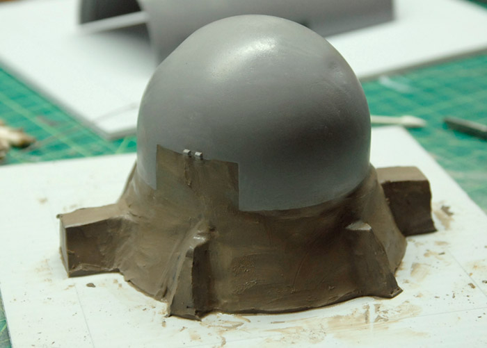
For the largest parts, including the two halves of the body and the head dome, the molds were still just two parts, but they required a bit more engineering in order to be sure that they could support their own weight later on. My fear was that if they were not thick enough, they would sag and close off the narrow space between the two halves of the mold, thinning the final part. For a few of the halves, I ended up enclosing a few scrap metal rods inside the mold in order to add support, which seemed to work decently.
Below you can see the head dome, getting prepped for pouring the first half of the mold.
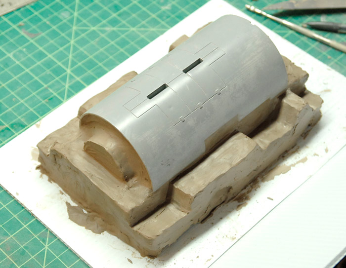
Similarly, one of the body halves, on its little bed of clay, ready for mold walls and some silicon.
Once the molds were made, I did a bit of testing with casting. First off, I tried to pour some resin into my new molds to see how it turned out without using any fancy tricks. Below you can see some freshly-poured resin, which pours clear and turns opaque white as it cures.
What I discovered is that while this lazy casting works pretty well for the larger, thicker parts, it doesn’t work as well for the smaller thinner things. Air bubbles tended to get trapped in the thinner parts, resulting in unusable castings. So, the next step was to move on to pressure casting. This entails pouring resin into the molds and then putting those molds into a pressure chamber and cranking up the pressure. This both pushes the resin down into the molds and also compresses any bubbles down to tiny sizes, making them much less of an issue. If this is combined with vacuum degassing of the resin, you get the best of both worlds, with nearly bubble-free resin squished down into the molds.
While I don’t have any good pictures of my pressure casting setup, it was decidedly DIY. I purchased an inexpensive pressure chamber (from Harbor Freight) that is intended for painting and then did all the things that the warning labels tell you not to do. I took most all of the fittings off of it, plugged up most of the holes, and removed the paint intake tube. The end result being a pressure pot that has a fitting to attach an air hose, a pressure gauge, and a valve that can vent the chamber. Combine this with an average-power air compressor and I’ve got a pressure casting setup!
The tricky part here was that the resin I was using has a pot life (time between mixing and curing) of about 7 minutes, during which I needed to vacuum degas the resin, pour it into the molds (which was complicated in a few cases), and then get it into the pressure chamber and under pressure, all before it starts to thicken. To help pack the most into the pressure chamber (which wasn’t very large), I built a little shelf that I could load up and drop into the pot. It was just a couple round pieces of wood held apart by long threaded rods with some nuts on them. Below you can see the shelf (with the top shelf removed), and various molds, after removal from the pressure pot.
This allowed me, if everything went perfectly, to make one kit worth of parts in three cycles of the pressure chamber. Unfortunately, there are a few parts that are tricky to get good castings of (like the hands), so often I’ve got to try those a couple of times in order to get a set of good parts.
That’s the basics of my adventure in building up a model kit on my own. Keep an eye out for a near-future blog post with a bit about the finished parts, some casting tricks and photos of the first finished model in grey primer.
Thanks for reading!
A good friend of mine, Neil Blevins, along with Bill Zahn, Stephan Bugaj, and a collection of concept art all-stars, have been working on an ‘art of’ book of sorts. For those unfamiliar, an ‘art of’ book is usually a book that contains the concept art for a film, television series, or something similar, i.e. ‘The Art of Inside Out’ or ‘The Art of Game of Thrones.’ The big difference here is that this book is full of art for a production that has not yet been made. They’ve been painting images and writing a story for a few years and this presented an opportunity for me to add my own bit of flavor to the mix.
I’d been interested in trying my hand at producing a garage resin model kit for a while, so that I could learn a bit more about the process. I talked to Neil about such a project and we decided that I would take his digital 3d model of the main character, who is a can-shaped robot, and see if I could turn it into a model kit. This blog post is about some of that process.
First off, I received a 3d file from Neil, which was the version of the main character that he was using to digitally render images from. It was set up to look good in pictures, but had lots of fine detail and various features that would be tricky to turn into physical object. Neil and I had agreed that we’d like to aim for a completed model that was 8-10 inches tall, which meant roughly 1/18 scale for this character (it was meant to be a pretty large robot). So, it fell to me to take his digital 3d model and figure out how to shrink it down, alter it and cut it up so that it could both be 3d printed and then replicated in resin, and then actually print it, clean up the prints, make molds of the parts, make castings from those molds and finally put at least one kit together so that Neil could put images of it into the book that they were working on.
Here are a few views of the digital model that I was working from.
Before jumping into the bulk of the work, I did a bit of a test. The robot had a weapon of sorts that was part gun and part spot welder. It was a fairly complex shape, with both thick and thin areas and would make a decent trial for the printing, clean up and mold making. After a few additions in the 3d file, to bridge some gaps, add some support and make it a little more mold friendly (less undercuts), I had the gun printed at Shapeways. Below you can see the print I got back, sprayed with an initial coat of primer.
The print itself was a little rough in a few areas, so it required a few cycles of priming and sanding, in order to fill in and smooth out the striations that the printing left behind. Below you can see a close up of one such area and the ridges on the flat surfaces that should be smooth.
With that test done, and a few lessons learned (how to keep print costs down, basic mold pouring techniques learned, etc), I moved on to a few more pieces. Below you can see the head, split into three parts, as they arrived from the printer. They come in a clear plastic that makes it difficult to see the texture from the printing process. This is why I primed the parts before sanding, as otherwise it was nearly impossible to see if the surface was smooth or not.
Here is how they go together, just press-fit in this photo:
Once the long and dull process of prepping all of the parts for mold making was complete, I split the mold making process into two main groups: single-piece molds and two-piece molds. The single-piece molds are for relatively flat parts, that only have detail on one side. The parts can be attached to a board, have a little box built around them and the silicon poured over them. The two-piece molds are for parts that have detail all around them. Those are more complicated to make molds for and require a form be built up around them with something like clay, defining where the mold seam will be. A pour spout and registration indentations need to be added so that the mold halves align and there is a place to pour in the resin in the finished mold.
First though, a bit about this process: Since the intent here is to make resin castings, using silicon rubber as the mold material, the requirements are a little different than if I were making molds for something like injection molded plastic kits. The silicon has a great deal of flexibility, so there can be some undercuts on the piece to be cast, and you don’t have to worry about the piece getting stuck in the mold. Also, basic molding and casting with these materials don’t strictly require any special equipment, although the addition of a few small machines can help the quality level a great deal.
In my case, I opted to supplement my process with the addition of a vacuum pump, a vacuum chamber, a pressure vessel and air compressor. I’ll go into more detail on those a bit later.
For the mold making, I started by ordering a box of corrugated plastic sheet. This stuff is commonly used for signs, but it is easy to cut, reasonably strong and inexpensive. For the one-part molds, I simply put a sheet down, hot-glued my parts to the sheet, and then built little walls around each part that would hold in the silicon. Those walls were hot-glued to the base and any gaps sealed up with more hot glue.
From what I had read, the mold should be at least 3/4” thick from the highest bit of the part being cast. I measured and marked on the walls of each box so I knew where to pour to. Now, when pouring a silicon mold, you’ll get the best mold quality if you eliminate bubbles from the silicon. Additionally, if you would like to pressure cast later on, you MUST get rid of the air bubbles in the silicon or they will give you a bumpy surface on your casting. There are a few ways to eliminate or minimize bubbles: pouring slowly into one corner of the mold (easy way, but not good for pressure casting), and vacuum degassing (harder, requires equipment, but good for pressure casting).
There is lots of information out there about mold making with silicon and casting with resin, so I’ll gloss over most of this. See the end of this post for links to various information sources to learn more.
The executive summary is that pouring your silicon from a little bit of a height (maybe 6 inches) and fairly slowly prevents bubbles from forming around your object, so you get good fidelity, but it does not prevent bubbles from forming in the silicon itself. So, if you are going to just pour resin into your mold and let it cure, this works just fine. If you are intending to pressure cast, you’ll need to get all the bubbles out of the silicon as well, so that requires another step: vacuum degassing. This is the technique of putting your mixed silicon under vacuum so that all the air bubbles expand and rise to the top, leaving your silicon bubble-free. If you skip this step, and pressure cast later, you’ll get what are commonly called ‘measles’ on the casting. These are when the bubbles in the silicon shrink under the pressure, and make little bumps on the casting, which you have to clean up later.
Since my goal was to be able to make the highest quality parts possible, I decided to invest in a bit of new equipment. This consisted of a vacuum chamber and a vacuum pump. This allows me to mix up a batch of silicon, put it into the vacuum chamber, place it under vacuum for a few minutes, watch all the air bubble out, and THEN pour it into my mold forms. Below you can see my setup and a batch of silicon bubbling away under vacuum.
After the single-piece molds were poured and cured, and a test casting or two had been done, it was time to move on to the larger and more complex multi-piece molds. For these, I got a box of water-based clay to use to build up half of each mold. Below you can see the arms and legs in their molds, ready for the first part to be poured. You can see how there are a few divots and grooves to be used for registration as well as little lumps that will be the pour spouts at the top of each part. You can also see the final state of the 3d printed parts, after they had been sanded and primed a few times and then finally had a gloss clear coat sprayed onto them, in order to get a smoother finish on the cast parts.
After pouring the first half, the molds are pulled off of their bases (but the sides left in place), the water-based clay washed away, some mold release agent sprayed on, and the other half of the mold poured. Below you can see a bunch of the other pieces ready for their second mold halves to be poured. On the lower left you can see the feet and their pour spouts that are plastic instead of clay, and the face plate and mouth in the center lower row, where I’m connecting two parts in one mold for faster casting later.
For the largest parts, including the two halves of the body and the head dome, the molds were still just two parts, but they required a bit more engineering in order to be sure that they could support their own weight later on. My fear was that if they were not thick enough, they would sag and close off the narrow space between the two halves of the mold, thinning the final part. For a few of the halves, I ended up enclosing a few scrap metal rods inside the mold in order to add support, which seemed to work decently.
Below you can see the head dome, getting prepped for pouring the first half of the mold.
Similarly, one of the body halves, on its little bed of clay, ready for mold walls and some silicon.
Once the molds were made, I did a bit of testing with casting. First off, I tried to pour some resin into my new molds to see how it turned out without using any fancy tricks. Below you can see some freshly-poured resin, which pours clear and turns opaque white as it cures.
What I discovered is that while this lazy casting works pretty well for the larger, thicker parts, it doesn’t work as well for the smaller thinner things. Air bubbles tended to get trapped in the thinner parts, resulting in unusable castings. So, the next step was to move on to pressure casting. This entails pouring resin into the molds and then putting those molds into a pressure chamber and cranking up the pressure. This both pushes the resin down into the molds and also compresses any bubbles down to tiny sizes, making them much less of an issue. If this is combined with vacuum degassing of the resin, you get the best of both worlds, with nearly bubble-free resin squished down into the molds.
While I don’t have any good pictures of my pressure casting setup, it was decidedly DIY. I purchased an inexpensive pressure chamber (from Harbor Freight) that is intended for painting and then did all the things that the warning labels tell you not to do. I took most all of the fittings off of it, plugged up most of the holes, and removed the paint intake tube. The end result being a pressure pot that has a fitting to attach an air hose, a pressure gauge, and a valve that can vent the chamber. Combine this with an average-power air compressor and I’ve got a pressure casting setup!
The tricky part here was that the resin I was using has a pot life (time between mixing and curing) of about 7 minutes, during which I needed to vacuum degas the resin, pour it into the molds (which was complicated in a few cases), and then get it into the pressure chamber and under pressure, all before it starts to thicken. To help pack the most into the pressure chamber (which wasn’t very large), I built a little shelf that I could load up and drop into the pot. It was just a couple round pieces of wood held apart by long threaded rods with some nuts on them. Below you can see the shelf (with the top shelf removed), and various molds, after removal from the pressure pot.
This allowed me, if everything went perfectly, to make one kit worth of parts in three cycles of the pressure chamber. Unfortunately, there are a few parts that are tricky to get good castings of (like the hands), so often I’ve got to try those a couple of times in order to get a set of good parts.
That’s the basics of my adventure in building up a model kit on my own. Keep an eye out for a near-future blog post with a bit about the finished parts, some casting tricks and photos of the first finished model in grey primer.
Thanks for reading!
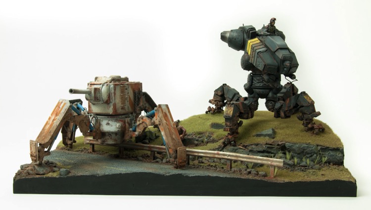
Walking Tanks Are Done!
14 - July - 2014 - 19:59
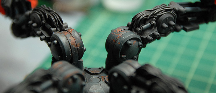
Another project wrapped up! Unfortunately I was super lazy when it came to taking progress photos of the rest of the build. But, rest assured that it was more of the same. The MIG tank (older looking one) was sprayed with red, stippled with rust colors, sprayed with hairspray, and then over-coated with a cream color and some orange stripes. The same chipping technique was used there as on the Rook (futuristic one). Lots of pigment was added to both in order to dirty them up, as well as a wash or two of dark, in order to bring out the details.
On the diorama, I added a bit of dirt and some sprigs of longer grass between the rocks. The figures were painted and added in there as well.
With all that said, let's get on to the photos! Click on the image below to get to the gallery, or click on the menu on the side bar.
On the diorama, I added a bit of dirt and some sprigs of longer grass between the rocks. The figures were painted and added in there as well.
With all that said, let's get on to the photos! Click on the image below to get to the gallery, or click on the menu on the side bar.
Hairspray and High Voltage!
13 - May - 2014 - 21:37
In this post, I'm going to cover just two things: a new (to me) weathering technique that uses hairspray and the construction of a DIY electrostatic grass tool. Both of these things were totally new to me, although I had read a good bit about the hairspray use and had watched a video about the grass tool.
First, the hairspray: The basic premise of hairspray weathering is to spray a base coat of paint in a color that you want to see when the top coat chips away. Then, once that is dry, you give your model a few coats of the cheapest hairspray you can find. Once that is totally dry, you spray on a your top coats. Then, you can wet areas of the model, the water will soak right through your top coat (I think this only works with acrylics) and will soften the hairspray. You can then poke at your paint with a toothpick, cotton swap, etc and the top coat will chip off, revealing the under coat. Magical paint chips!!
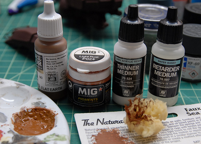
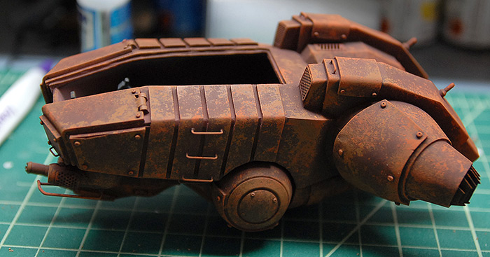
To start with, I sprayed my model with Tamiya Hull Red as the base coat. Next, to break up the paint, and add some dirt/rust details, I mixed up a batch of paint that consisted of mostly Vallejo Flat Earth, with some MIG pigment in Light Rust. In order to keep it from getting too thick and to keep with workable for longer, I added a small amount of Vallejo Retarder Medium (slows drying) and Thinner Medium (reduces thickness).
I used a small piece of natural sponge to dab it all over the model. After the first pass, I added a bit of Standard Rust pigment to the paint mix to get a redder shade and went back over the model again. Below you can see the model after all the under coat was applied.
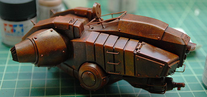
Next I took it outside and gave it two or three coats of hairspray. Be generous, as it doesn't seem to bulk up and shouldn't add any strange texture. If you wanted to prevent some areas from chipping at all, I'm sure you could mask them. As far as what sort of hairspray to use, I don't think it matters much (I'm no hairspray expert), so I recommend just getting the biggest/cheapest can you can find. If there is such a thing as waterproof hairspray (Google says there is), you do NOT want that. The whole premise of this technique is that the water dissolves the hairspray later, so if you used waterproof hairspray, you'd be out of luck when it came time to chip the paint.
Below you can see my model with the hairspray applied and dry. It dried to a semigloss finish.
Next came the top coat. In my case, I first put down a coat of light grey, with the thought that it would make for more interesting chipping later as well as give me a more neutral base to paint over. Next I used Tamiya Field Blue as the main color, and then went back and lightened the panel centers with the same color mixed with a bit of light grey.
Then the fun began! For water application, I just used a cotton swab, and painted water on a small area at a time. I would swab on some water, wait a few minutes (the paint texture changes a bit once the water is soaked in) and then I scraped it a bit with a wooden toothpick that had been cut to a chisel point. I thought it worked great! In fact, I had to be careful not to take off too much of the top coat, as once the hairspray is wet, it is very easy to get the paint off.
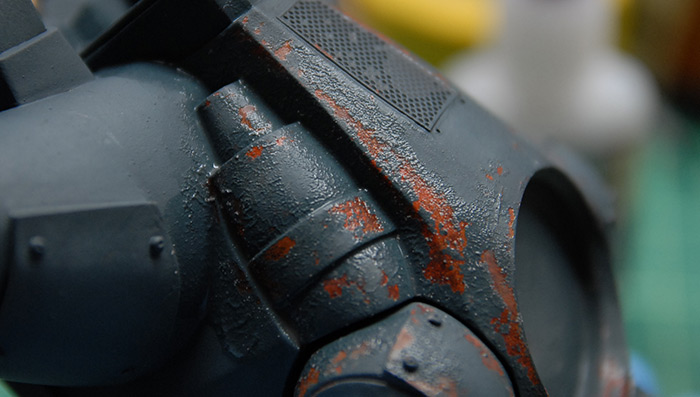
Below you can see some finished chipping on the tank legs.
Below you can see how the paint texture changes once the hairspray is wet and the paint is ready to scrape. Fortunately, the paint does flatten back out once things dry. The only catch is that the hairspray does mix in with the water during the process and once things dry, some of the semi-gloss finish that we saw earlier will be present on top of the flat paint. Nothing a bit of Testors Dullcoat won't fix later.
Next we turn back to the base. Before I could get to grass application, I needed to paint it. I was going to follow the standard order of preshade-with-dark, main color coat, sponge to break up some areas and dry brush to pull out details.
Below you can see the first pass of pre-shading.
Next was the various color passes. My idea was to try to make this look like an old unused road, so I masked the road lines off and just dry brushed the lines on, so they were old and faded looking. Everything will get a good deal more dust and weathering later on, in order to blend it all together.
I was hoping to use electro static grass on this base, in order to get some nice grass on the upper area and in the nooks and crannies around the rocks. I knew there were various devices that one could buy in order to apply the grass and get it to stick up nicely. Once I actually went to BUY one of these tools, I was in for a bit of sticker shock. As much as I enjoy getting a good tool, I couldn't justify spending $150+ just to do my little diorama. With a bit of searching around, I ran across a video on youtube showing how to build your own grass applicator using a few cheap parts and a little bit of work. I decided to give it a try.
Here is the video I watched first, if you'd like to give it a try. Have a watch and then see what I did afterwards.
I'm no electrical engineer, but here's a little bit about how some of this stuff works, as I understand it. The bug zapper that I ended up with takes two AA batteries. If you touch both ends of a AA battery, you don't get shocked. The 1.5 volts that that battery puts out is not enough to get through your skin, bones, etc. Even stacking up the two batteries, giving you 3 volts, still doesn't result in a shock. So, in order to be able to zap bugs, the bug zapper has a small transformer in it that boosts that voltage up to something like 15000 volts. That ends up being enough to jump across small gaps and also fry bugs. The way the bug zapper works is that it then routes that current into the various layers of the racquet, which are spaced closely, but far enough apart that the current can't jump across. In the case of mine, the outer layers got the negative terminal and the inner layer got the positive. When you swing that thing as a bug, the bug passes through the holes and probably hits both layers or is close enough to both for the current to jump across the gap, through the bug, completing the circuit, and electrocuting the insect.
Our goal is not to electrocute anything, but instead use all the static electricity that is generated by that high voltage to make our grass all stand on end. With the ground of the zapper attached to the glue on the base of the diorama, and the positive current attached to the strainer, the static grass flocking should fall out of the strainer a few hairs at a time, stick to the glue on the base, and then stay standing up because they are attracted to the strainer's static charge, the same way your arm hairs stand up when you hold a statically charged balloon above them. So long as the glue is fairly thick and sticky, the hairs should just stay where ever they land, and you'll get a great looking patch of grass.
With that said, PLEASE BE CAREFUL. While I don't think this is strong enough to do any extreme damage, it is probably enough voltage to give you a good shock, a small burn, or some other unpleasant injury. If you decide to try this yourself, be very careful and don't leave any of this stuff laying about where a curious child could get ahold of it.
Okay, with the legal disclaimers out of the way, let's get down to business.
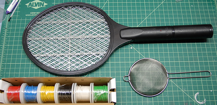
I was far lazier than the fellow in the video and just went to good ol Amazon for my parts. Since I've got Amazon Prime, I wasn't concerned about shipping cost, so I order up the following parts:
Zap Master Bug Zapper - $6.97
Stainless Steel Mesh Strainer - $6.71
Insulated Alligator Clips - $3.99
Insulated Solid Wire (lots) - $20
Obviously, I got way more wire than I needed, but it was time for me to stock up anyway, so you can ignore that one if you already have some wire laying about that you can use. Same with the alligator clips, as that $3.99 was for a pack of 10. Also, I bet you could find a cheaper mesh strainer at a local dollar store, if you were concerned about the budget or just wanted to keep it under $10. Below you can see the parts that I ended up with.
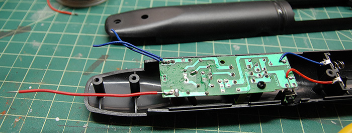
Taking the bug zapper apart (be sure there are no batteries in there!), you can see the circuit board that does the current transformation and that has the activation button on it. Unlike the zapper in the video, all the components on mine are under the board, so harder to see. The first order of business was to get rid of the old wires that came off the board and replace them with tougher and longer ones. This requires desoldering the old wires, and in the case of my zapper, melting and soaking up some protective wax that was over the various contacts. Below you can see the board with my replacement red wire coming off the left side of the board. This will be the wire that will contact the metal strainer.
Once the longer ground wire is attached (I made mine roughly a foot long), I had to figure out how to attach the strainer. I had a bit of scrap aluminum around (from my bag of scrap bits that I got at the hardware store ages ago), so I just made two little strips, and drilled holes in the strips and in the handle of the zapper. The strainer handle needed to be cut a bit shorter in order to fit, and then the whole thing could be bolted together. I was originally going to solder the red wire to the strainer handle, but it ended up being easier to just sandwich the wire between one of the plates and the handle.
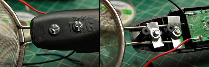
Next, I put the other side of the handle back on, and attached one of the alligator clips to the ground wire and I was ready to flock!
How this works, step by step:
1) Mix up your flocking grass. I mixed roughly equal parts 'Medium Green' and 'Burnt Grass' from Woodland Scenics in order to get a more natural mix of color.
2) Spread some undiluted scenic cement (or maybe Elmers white glue, or PVA glue) on to whatever you want to flock. Apply it in such a way that all the glue is contiguous. The electrical current needs to be able to get to all the glue, so no glue islands!
3) Poke a small nail into the glue somewhere (preferably somewhere that the little hole won't be noticed) and clip your negative wire to the nail.
4) Put some of the grass mix into your strainer bowl.
5) Hold your strainer bowl over the glue (a couple inches above, don't let them touch!), press and hold the button on the zapper handle (red light should illuminate), and gently shake your strainer over the glue until it is all covered.
6) Err on the side of too much grass, as you can always shake off the stuff that doesn't stick later and it is really hard to put another coat of grass on later, since you'd have to paint the glue on over your first coat of grass.
Following those steps, here is what I ended up with on my test patch:
As you can see, I left the glue off of the rock and the toe divots. I was pretty happy with how the grass stood up, but still felt fairly natural. If you wanted patchier grass colors, you could mix your grass colors a bit less that I did, so you got clumps in the strainer, which should give you areas with a bit more of one color or another as you go.
Below is a side view of the same area as above.
And that is that! Next up for me is some weathering on the base, and painting on the other tank.
Thanks for reading!
First, the hairspray: The basic premise of hairspray weathering is to spray a base coat of paint in a color that you want to see when the top coat chips away. Then, once that is dry, you give your model a few coats of the cheapest hairspray you can find. Once that is totally dry, you spray on a your top coats. Then, you can wet areas of the model, the water will soak right through your top coat (I think this only works with acrylics) and will soften the hairspray. You can then poke at your paint with a toothpick, cotton swap, etc and the top coat will chip off, revealing the under coat. Magical paint chips!!
To start with, I sprayed my model with Tamiya Hull Red as the base coat. Next, to break up the paint, and add some dirt/rust details, I mixed up a batch of paint that consisted of mostly Vallejo Flat Earth, with some MIG pigment in Light Rust. In order to keep it from getting too thick and to keep with workable for longer, I added a small amount of Vallejo Retarder Medium (slows drying) and Thinner Medium (reduces thickness).
I used a small piece of natural sponge to dab it all over the model. After the first pass, I added a bit of Standard Rust pigment to the paint mix to get a redder shade and went back over the model again. Below you can see the model after all the under coat was applied.
Next I took it outside and gave it two or three coats of hairspray. Be generous, as it doesn't seem to bulk up and shouldn't add any strange texture. If you wanted to prevent some areas from chipping at all, I'm sure you could mask them. As far as what sort of hairspray to use, I don't think it matters much (I'm no hairspray expert), so I recommend just getting the biggest/cheapest can you can find. If there is such a thing as waterproof hairspray (Google says there is), you do NOT want that. The whole premise of this technique is that the water dissolves the hairspray later, so if you used waterproof hairspray, you'd be out of luck when it came time to chip the paint.
Below you can see my model with the hairspray applied and dry. It dried to a semigloss finish.
Next came the top coat. In my case, I first put down a coat of light grey, with the thought that it would make for more interesting chipping later as well as give me a more neutral base to paint over. Next I used Tamiya Field Blue as the main color, and then went back and lightened the panel centers with the same color mixed with a bit of light grey.
Then the fun began! For water application, I just used a cotton swab, and painted water on a small area at a time. I would swab on some water, wait a few minutes (the paint texture changes a bit once the water is soaked in) and then I scraped it a bit with a wooden toothpick that had been cut to a chisel point. I thought it worked great! In fact, I had to be careful not to take off too much of the top coat, as once the hairspray is wet, it is very easy to get the paint off.
Below you can see some finished chipping on the tank legs.
Below you can see how the paint texture changes once the hairspray is wet and the paint is ready to scrape. Fortunately, the paint does flatten back out once things dry. The only catch is that the hairspray does mix in with the water during the process and once things dry, some of the semi-gloss finish that we saw earlier will be present on top of the flat paint. Nothing a bit of Testors Dullcoat won't fix later.
Next we turn back to the base. Before I could get to grass application, I needed to paint it. I was going to follow the standard order of preshade-with-dark, main color coat, sponge to break up some areas and dry brush to pull out details.
Below you can see the first pass of pre-shading.
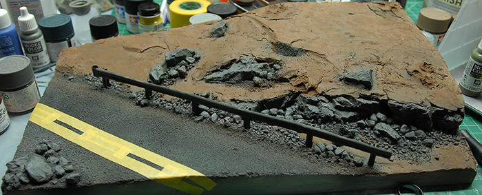
Next was the various color passes. My idea was to try to make this look like an old unused road, so I masked the road lines off and just dry brushed the lines on, so they were old and faded looking. Everything will get a good deal more dust and weathering later on, in order to blend it all together.
I was hoping to use electro static grass on this base, in order to get some nice grass on the upper area and in the nooks and crannies around the rocks. I knew there were various devices that one could buy in order to apply the grass and get it to stick up nicely. Once I actually went to BUY one of these tools, I was in for a bit of sticker shock. As much as I enjoy getting a good tool, I couldn't justify spending $150+ just to do my little diorama. With a bit of searching around, I ran across a video on youtube showing how to build your own grass applicator using a few cheap parts and a little bit of work. I decided to give it a try.
Here is the video I watched first, if you'd like to give it a try. Have a watch and then see what I did afterwards.
I'm no electrical engineer, but here's a little bit about how some of this stuff works, as I understand it. The bug zapper that I ended up with takes two AA batteries. If you touch both ends of a AA battery, you don't get shocked. The 1.5 volts that that battery puts out is not enough to get through your skin, bones, etc. Even stacking up the two batteries, giving you 3 volts, still doesn't result in a shock. So, in order to be able to zap bugs, the bug zapper has a small transformer in it that boosts that voltage up to something like 15000 volts. That ends up being enough to jump across small gaps and also fry bugs. The way the bug zapper works is that it then routes that current into the various layers of the racquet, which are spaced closely, but far enough apart that the current can't jump across. In the case of mine, the outer layers got the negative terminal and the inner layer got the positive. When you swing that thing as a bug, the bug passes through the holes and probably hits both layers or is close enough to both for the current to jump across the gap, through the bug, completing the circuit, and electrocuting the insect.
Our goal is not to electrocute anything, but instead use all the static electricity that is generated by that high voltage to make our grass all stand on end. With the ground of the zapper attached to the glue on the base of the diorama, and the positive current attached to the strainer, the static grass flocking should fall out of the strainer a few hairs at a time, stick to the glue on the base, and then stay standing up because they are attracted to the strainer's static charge, the same way your arm hairs stand up when you hold a statically charged balloon above them. So long as the glue is fairly thick and sticky, the hairs should just stay where ever they land, and you'll get a great looking patch of grass.
With that said, PLEASE BE CAREFUL. While I don't think this is strong enough to do any extreme damage, it is probably enough voltage to give you a good shock, a small burn, or some other unpleasant injury. If you decide to try this yourself, be very careful and don't leave any of this stuff laying about where a curious child could get ahold of it.
Okay, with the legal disclaimers out of the way, let's get down to business.
I was far lazier than the fellow in the video and just went to good ol Amazon for my parts. Since I've got Amazon Prime, I wasn't concerned about shipping cost, so I order up the following parts:
Zap Master Bug Zapper - $6.97
Stainless Steel Mesh Strainer - $6.71
Insulated Alligator Clips - $3.99
Insulated Solid Wire (lots) - $20
Obviously, I got way more wire than I needed, but it was time for me to stock up anyway, so you can ignore that one if you already have some wire laying about that you can use. Same with the alligator clips, as that $3.99 was for a pack of 10. Also, I bet you could find a cheaper mesh strainer at a local dollar store, if you were concerned about the budget or just wanted to keep it under $10. Below you can see the parts that I ended up with.
Taking the bug zapper apart (be sure there are no batteries in there!), you can see the circuit board that does the current transformation and that has the activation button on it. Unlike the zapper in the video, all the components on mine are under the board, so harder to see. The first order of business was to get rid of the old wires that came off the board and replace them with tougher and longer ones. This requires desoldering the old wires, and in the case of my zapper, melting and soaking up some protective wax that was over the various contacts. Below you can see the board with my replacement red wire coming off the left side of the board. This will be the wire that will contact the metal strainer.
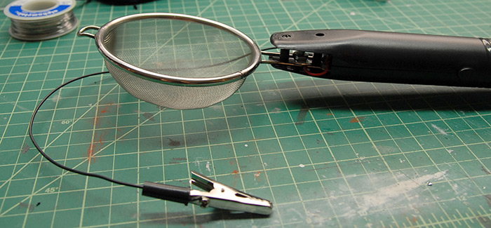
Once the longer ground wire is attached (I made mine roughly a foot long), I had to figure out how to attach the strainer. I had a bit of scrap aluminum around (from my bag of scrap bits that I got at the hardware store ages ago), so I just made two little strips, and drilled holes in the strips and in the handle of the zapper. The strainer handle needed to be cut a bit shorter in order to fit, and then the whole thing could be bolted together. I was originally going to solder the red wire to the strainer handle, but it ended up being easier to just sandwich the wire between one of the plates and the handle.
Next, I put the other side of the handle back on, and attached one of the alligator clips to the ground wire and I was ready to flock!
How this works, step by step:
1) Mix up your flocking grass. I mixed roughly equal parts 'Medium Green' and 'Burnt Grass' from Woodland Scenics in order to get a more natural mix of color.
2) Spread some undiluted scenic cement (or maybe Elmers white glue, or PVA glue) on to whatever you want to flock. Apply it in such a way that all the glue is contiguous. The electrical current needs to be able to get to all the glue, so no glue islands!
3) Poke a small nail into the glue somewhere (preferably somewhere that the little hole won't be noticed) and clip your negative wire to the nail.
4) Put some of the grass mix into your strainer bowl.
5) Hold your strainer bowl over the glue (a couple inches above, don't let them touch!), press and hold the button on the zapper handle (red light should illuminate), and gently shake your strainer over the glue until it is all covered.
6) Err on the side of too much grass, as you can always shake off the stuff that doesn't stick later and it is really hard to put another coat of grass on later, since you'd have to paint the glue on over your first coat of grass.
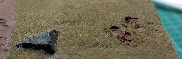
Following those steps, here is what I ended up with on my test patch:
As you can see, I left the glue off of the rock and the toe divots. I was pretty happy with how the grass stood up, but still felt fairly natural. If you wanted patchier grass colors, you could mix your grass colors a bit less that I did, so you got clumps in the strainer, which should give you areas with a bit more of one color or another as you go.
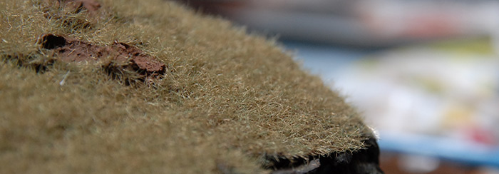
Below is a side view of the same area as above.
And that is that! Next up for me is some weathering on the base, and painting on the other tank.
Thanks for reading!
Continuing Construction
13 - May - 2014 - 19:23
At the end of the last blog post, I had just tacked everything together and tested to be sure it all fit properly. The next step was to solidify all the leg joints and make both models able to support their own weight. So, without further ado, let's get right to it:
Below you can see all of the legs glued in place. For the tan legs on the right, this was a fairly simple matter of cutting the pistons to the correct length and then epoxying them in place. For the grey legs, I left them in place on the base and dripped a bit of thin CA glue into each joint, so that each leg was locked into its correct position.
Since that thin layer of CA isn't really going to hold up very well once weight is put on it, I then spent some time drilling holes through each joint and inserting brass rod. The idea was to get the rod all the way through each joint without actually poking out the other side. My hope was that this would give the joints something better than the friction of the CA glue to support them. So far, it has worked very well.
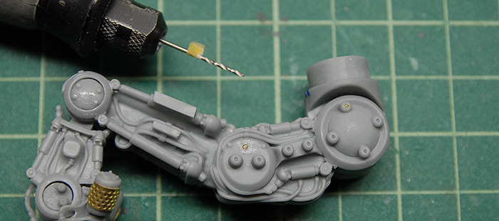
Below you can see a tiny drill bit mounted in the Dremel extension thing (easier to handle in small spaces than the whole Dremel). The little tape tab is there so I know how deep to drill.
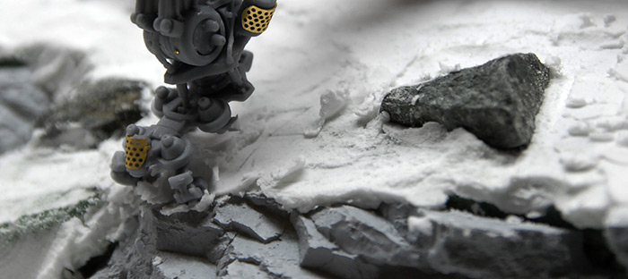
Once the legs were all locked in place, I put a little extra spackle on the base and squished each foot into the ground so that they had little footprints to fit in to. This both made it look like the model is heavy enough that it is digging into the ground and gives me registration marks so that I know exactly where the model is supposed to fit onto the base. Below you can also see a missing toe on this foot. I have no idea where it went! I didn't notice when it broke off and, despite searching all over the place, I couldn't find it. So, I'm just going to put some extra rust there later and pretend like it is supposed to be like that.
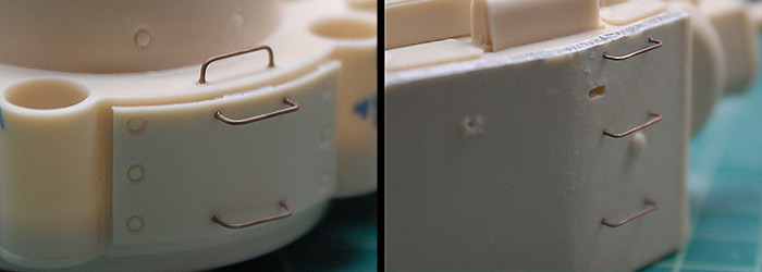
Moving along to the leg armor plates, a number of them called for grab handles. This was just regular old brass rod, bent to shape.
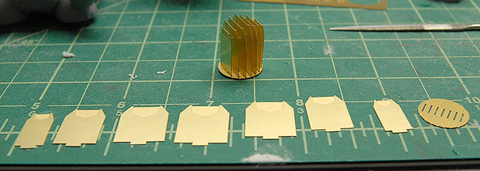
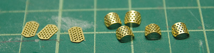
The photo etch that comes with this kit is interesting in that it builds up into large shapes that fit into some of the vents on the upper body of the tank. Below you can see the component parts and assembled collection that fit into the main exhaust tubes.
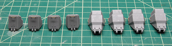
There are similar etch assemblies in the smaller square vents. These fit well, but had the tendency to fall through the holes they were supposed to cover. As you can see below, I just glued on a few strips of styrene in order to give them a little lip on each side and keep them in place.
The instructions also pointed out various places where wire grab handles should be added. Like on the leg armor, these were just simple bent brass wire. In this case, though, the wire that I was using was a bit brittle and tended to snap when bent. In order to soften it up a bit, I annealed it with a torch. For those unfamiliar with this process, I took the brass wire in some pliers (it gets hot!) and slowly passed it through the flame of a butane torch. The goal is to get the metal red hot, but not so hot that it starts to come apart or distort. Letting the metal cool in the air results in a much more pliable bit of wire. The wire is far softer and much easier to bend.
With that done, it was time to start putting everything together. Below you can see the leg armor plates held in place while epoxy cures.
Below you can see the legs clamped in place while the epoxy cures. If you look at the base of the lower left leg, you can see various marks. I put those on there to keep the legs sorted, so that I knew which one went in which spot and at which angle. This should, in theory, result in the legs all being just right when I place the model back on the base.
I say, "in theory" because, after everything was glued and assembled, I placed the model back on the base and the leg that was in the left corner was hovering about 3/8 of an inch off the ground. Not sure if there was a good way to fix it, I decided that that was a good place for a rock!
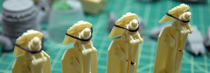
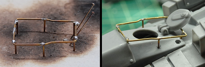
Back on the future-y tank, the kit had come with a photo etch version of a little railing around the hatch. Given the scale, though, this rail seemed much too thin. I decided to have a go at building my own version from some brass rod and solder. I tried a few methods of soldering using the tools that I had, but it was pretty messy and I managed to incinerate a few pieces of rod by accident. What you can see below is the second version (the blackened surface came from the first version). I have since read a brief article in Fine Scale Modeler magazine about working with brass, so the next time I do, I'll be a bit better off. Anyway, with a bit of filing and sanding, some drilling on the resin, and a spot of CA glue, the railing was cleaned up and attached around the hatch.
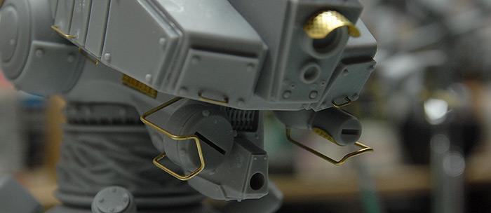
A bit more wire bending got me some protective bars around the sensitive equipment hanging under the front end of this tank.
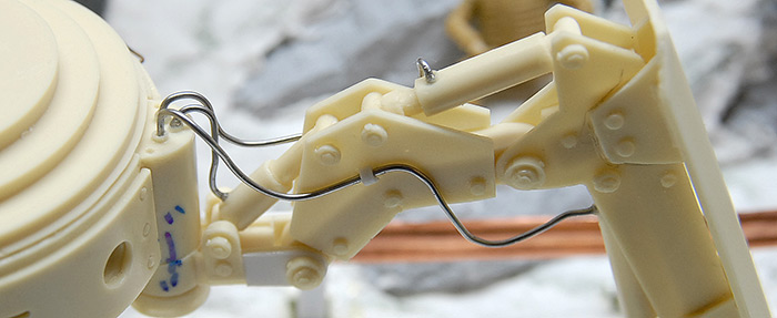
Similarly, the other kit came with some plastic-coated wire to act as hydraulic hosing for the leg pistons. Unfortunately, this wire was not easily shapable and when added, really seemed out of scale. Having just done a bit of soldering on the other tank, I decided to replace the kit wire with some thin solder, since it is so easily shapable. Also, instead of just letting it hang free (which seemed implausible to me, as far as tank design goes), I added a few styrene brackets on the sides of the joint plate, so that it looked like the hosing was held in place.
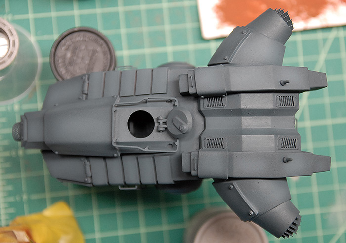
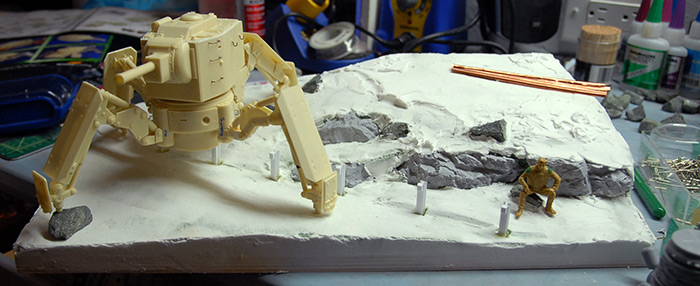
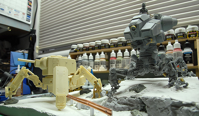
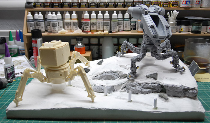
And, with the exception of the gatling gun that goes on the front of the grey tank (and that is fragile!), that wraps up construction on the two models. Below you can see the unprimed models, on the incomplete base.
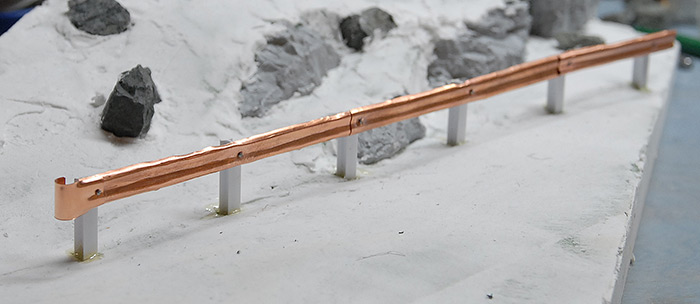
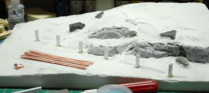
Turning back to the diorama base, it was time to start adding things to it. First was the guard rail. If you recall from the last post, this was made from some sheet copper that I had in a bag of scrap metal bits. In order to attach it to the styrene posts, I just used a small drill bit in the Dremel and drilled through the copper, into the posts. I then made some small bolts out of the top 1/8" of straight pins and used those, with some thick CA, to attach the metal parts.
Next up, it was time to add some different sizes of rocks, gravel and sand in order to start to blend things all together. I picked up a few bags of model railroad decoration from the local hobby shop.

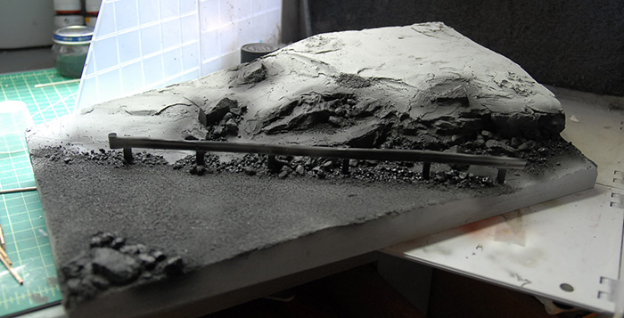
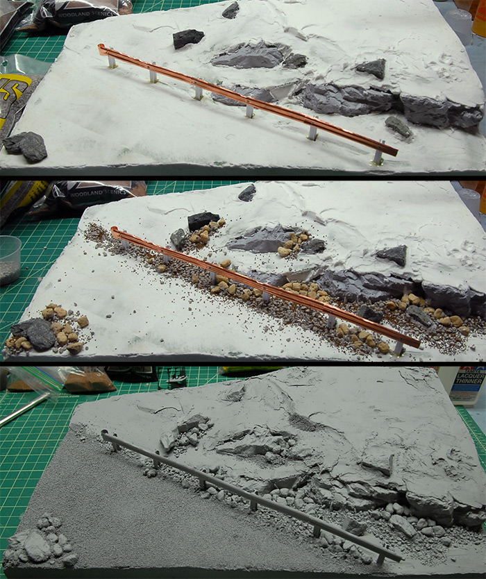
Below you can see the three stages, from clean to primed. I simply worked from large to small. First I added the largest size of rock, clustering them around the base of the hill, then the next size down, clustered around the larger rocks, etc. I decided that the road needed a bit of texture, as the base spackle was just too smooth. I was going with the premise that this bit of road has been long since abandoned, so it wouldn't be super clean and smooth. So what I did was to add a layer of the finest gravel/sand that I had onto the road surface. It ended up a little bit rougher than I had hoped, but I think I'll be able to make up for that with a bit of weathering and dirt on the road later.
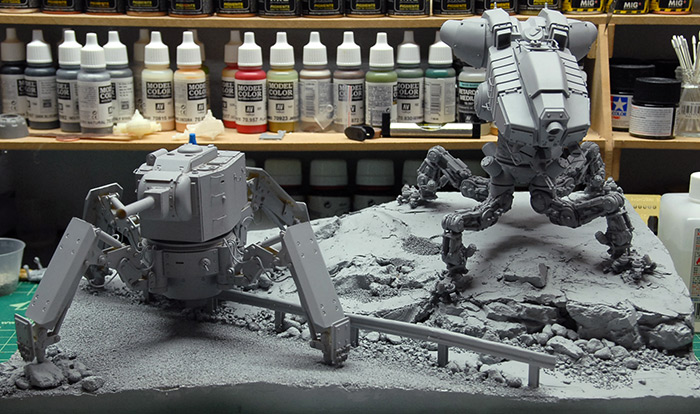
With a couple coats of primer on the tanks and base, that should wrap up construction. All that is left now is a great deal of painting and an attempt at flocked grass.
Tune in next time (very soon!) for my attempt at a new (to me) weathering technique and my shot at building a flocking device out of a few cheap parts.
Thanks for reading!
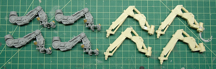
Below you can see all of the legs glued in place. For the tan legs on the right, this was a fairly simple matter of cutting the pistons to the correct length and then epoxying them in place. For the grey legs, I left them in place on the base and dripped a bit of thin CA glue into each joint, so that each leg was locked into its correct position.
Since that thin layer of CA isn't really going to hold up very well once weight is put on it, I then spent some time drilling holes through each joint and inserting brass rod. The idea was to get the rod all the way through each joint without actually poking out the other side. My hope was that this would give the joints something better than the friction of the CA glue to support them. So far, it has worked very well.
Below you can see a tiny drill bit mounted in the Dremel extension thing (easier to handle in small spaces than the whole Dremel). The little tape tab is there so I know how deep to drill.
Once the legs were all locked in place, I put a little extra spackle on the base and squished each foot into the ground so that they had little footprints to fit in to. This both made it look like the model is heavy enough that it is digging into the ground and gives me registration marks so that I know exactly where the model is supposed to fit onto the base. Below you can also see a missing toe on this foot. I have no idea where it went! I didn't notice when it broke off and, despite searching all over the place, I couldn't find it. So, I'm just going to put some extra rust there later and pretend like it is supposed to be like that.
Moving along to the leg armor plates, a number of them called for grab handles. This was just regular old brass rod, bent to shape.
The photo etch that comes with this kit is interesting in that it builds up into large shapes that fit into some of the vents on the upper body of the tank. Below you can see the component parts and assembled collection that fit into the main exhaust tubes.
There are similar etch assemblies in the smaller square vents. These fit well, but had the tendency to fall through the holes they were supposed to cover. As you can see below, I just glued on a few strips of styrene in order to give them a little lip on each side and keep them in place.
The instructions also pointed out various places where wire grab handles should be added. Like on the leg armor, these were just simple bent brass wire. In this case, though, the wire that I was using was a bit brittle and tended to snap when bent. In order to soften it up a bit, I annealed it with a torch. For those unfamiliar with this process, I took the brass wire in some pliers (it gets hot!) and slowly passed it through the flame of a butane torch. The goal is to get the metal red hot, but not so hot that it starts to come apart or distort. Letting the metal cool in the air results in a much more pliable bit of wire. The wire is far softer and much easier to bend.
With that done, it was time to start putting everything together. Below you can see the leg armor plates held in place while epoxy cures.
Below you can see the legs clamped in place while the epoxy cures. If you look at the base of the lower left leg, you can see various marks. I put those on there to keep the legs sorted, so that I knew which one went in which spot and at which angle. This should, in theory, result in the legs all being just right when I place the model back on the base.
I say, "in theory" because, after everything was glued and assembled, I placed the model back on the base and the leg that was in the left corner was hovering about 3/8 of an inch off the ground. Not sure if there was a good way to fix it, I decided that that was a good place for a rock!
Back on the future-y tank, the kit had come with a photo etch version of a little railing around the hatch. Given the scale, though, this rail seemed much too thin. I decided to have a go at building my own version from some brass rod and solder. I tried a few methods of soldering using the tools that I had, but it was pretty messy and I managed to incinerate a few pieces of rod by accident. What you can see below is the second version (the blackened surface came from the first version). I have since read a brief article in Fine Scale Modeler magazine about working with brass, so the next time I do, I'll be a bit better off. Anyway, with a bit of filing and sanding, some drilling on the resin, and a spot of CA glue, the railing was cleaned up and attached around the hatch.
A bit more wire bending got me some protective bars around the sensitive equipment hanging under the front end of this tank.
Similarly, the other kit came with some plastic-coated wire to act as hydraulic hosing for the leg pistons. Unfortunately, this wire was not easily shapable and when added, really seemed out of scale. Having just done a bit of soldering on the other tank, I decided to replace the kit wire with some thin solder, since it is so easily shapable. Also, instead of just letting it hang free (which seemed implausible to me, as far as tank design goes), I added a few styrene brackets on the sides of the joint plate, so that it looked like the hosing was held in place.
And, with the exception of the gatling gun that goes on the front of the grey tank (and that is fragile!), that wraps up construction on the two models. Below you can see the unprimed models, on the incomplete base.
Turning back to the diorama base, it was time to start adding things to it. First was the guard rail. If you recall from the last post, this was made from some sheet copper that I had in a bag of scrap metal bits. In order to attach it to the styrene posts, I just used a small drill bit in the Dremel and drilled through the copper, into the posts. I then made some small bolts out of the top 1/8" of straight pins and used those, with some thick CA, to attach the metal parts.
Next up, it was time to add some different sizes of rocks, gravel and sand in order to start to blend things all together. I picked up a few bags of model railroad decoration from the local hobby shop.
Below you can see the three stages, from clean to primed. I simply worked from large to small. First I added the largest size of rock, clustering them around the base of the hill, then the next size down, clustered around the larger rocks, etc. I decided that the road needed a bit of texture, as the base spackle was just too smooth. I was going with the premise that this bit of road has been long since abandoned, so it wouldn't be super clean and smooth. So what I did was to add a layer of the finest gravel/sand that I had onto the road surface. It ended up a little bit rougher than I had hoped, but I think I'll be able to make up for that with a bit of weathering and dirt on the road later.
With a couple coats of primer on the tanks and base, that should wrap up construction. All that is left now is a great deal of painting and an attempt at flocked grass.
Tune in next time (very soon!) for my attempt at a new (to me) weathering technique and my shot at building a flocking device out of a few cheap parts.
Thanks for reading!
Resin and More Resin!
25 - February - 2014 - 20:25
So, at the conclusion of my last post, I was all ready to spend a bunch of time practicing car paint finishes. Well, I did that briefly and discovered that it was pretty boring. Without a real end goal to aim for, I lost interest pretty quickly. So, since I am dealing with some resin-related things in a side project, I decided that I should to a side-by-side build of two resin kits that have been in my collection for a while. They are similarly themed, both being walking tank sorts of designs, but they are very different kits.
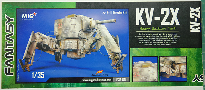
First of the two is a heavy walking tank kit from MIG Productions, who are more commonly known for their pigments:
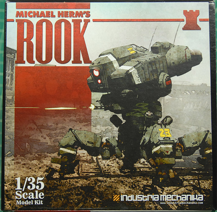
Along with that kit, I'll be building a more futuristic walking tank kit, the Rook, from Industria Mechanika:
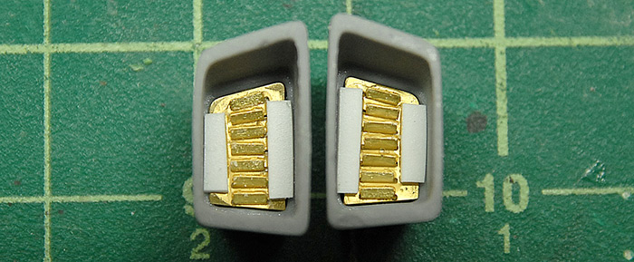
Before I get into construction, let's compare and contrast the two kits. Industria Mechanika's kit consists of a very large number of parts (many of which are in the bags seen below), cast in an opaque grey resin. This is accompanied by a few pieces if brass rod, to be bent into grab handles and two sheets of photo-etch. It also includes two figures in the form of pilots that fit into the cockpit seats.
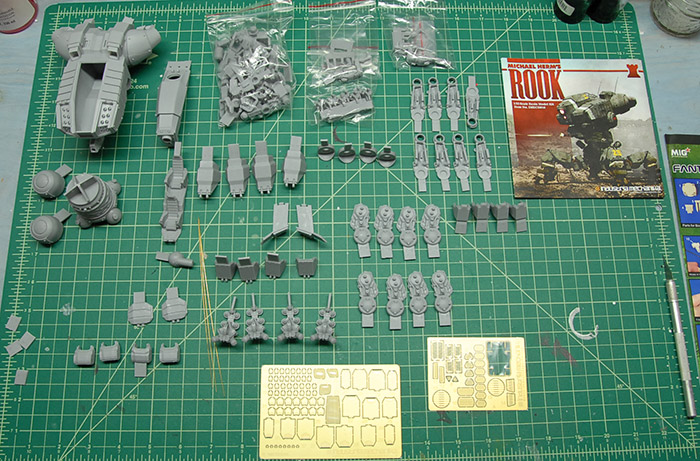
The casting quality is some of the best I've ever seen on a resin kit, with most of the parts having a small tab left on them, which doubles as part identification numbering. Generally, though, there are almost no large pour blocks on any of the parts. There are a few areas where a thin sheet of resin is left, that needs to be trimmed away, but I personally find this to be much easier than having to cut/sand a large block of resin away. The quality of the resin on this kit is very plastic-like, in that is is not too brittle and carves easily with an x-acto blade.
The MIG kit is cast from a tan resin, which is a bit more standard in cast resin parts. This kit is nearly all resin, with a bit of tubing for hydraulic hoses.
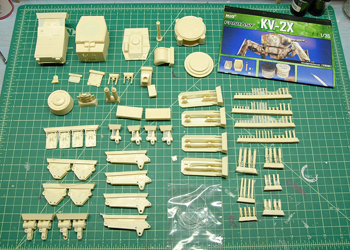
This resin is a bit more brittle than the grey resin seen above and has the more commonly found pour blocks, bubbles and need for a great deal of clean up. It also requires a good deal more shaping, drilling, etc in order to get it all to go together. Overall, though, the fidelity of the parts is still good. Below you can see some of the parts with their pour blocks still attached.
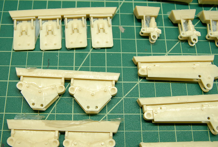
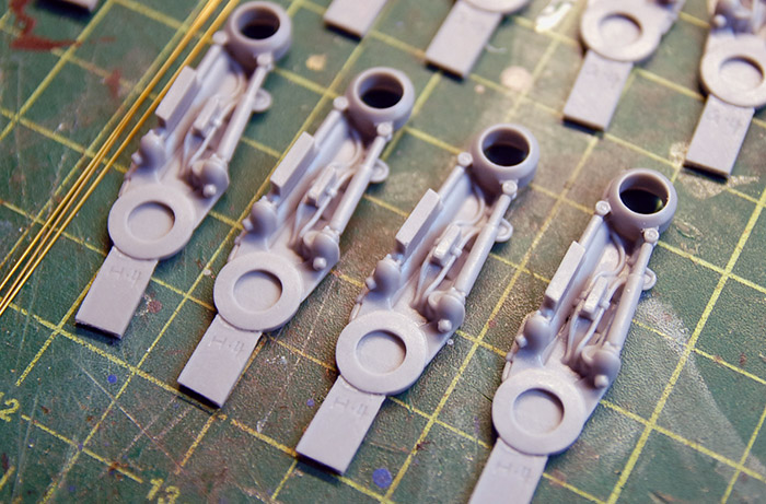
I decided to get started with the MIG model, beginning with the legs. I found that most of the leg length, on the outside, would eventually be covered by an armor plate, so I did a fairly rough clean up job. Below you can see the trimmed parts, with the various hinge holes drilled out.
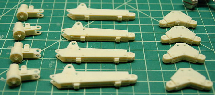
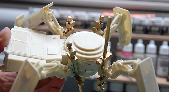
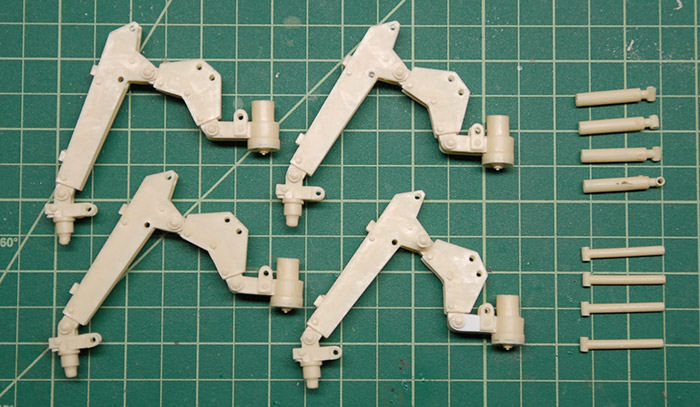
These legs are held together by resin pins that go through the drilled out holes. Then, the leg position is held by hydraulics, part of which needs to be cut to length. This means that each leg consists of four main parts and a bunch of pins and cylinders that hold the big parts together. Below you can see the four legs with the pins in (not glued yet), but without any of the hydraulics.
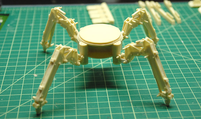
Next, I put the hydraulics in place, but just kinda stuck on there, so that the legs were easily positionable. Then, using some museum tack, I stuck the legs onto the central body part, making sure that they all fit, etc. Below you can see it standing on it's own (although precariously, since nothing has been glued yet).
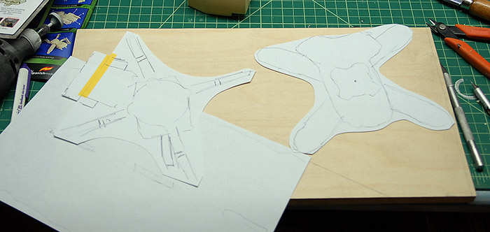
It was at this point that I realized that in order to be able to glue the legs into the correct positions, I'd need to know what they were standing on. This meant that I needed to stop the leg building and start figuring out what the diorama was going to look like. I decided on a rough base size, and then made myself some handy paper cutouts that were about the size of the finished tanks. In order to get an idea of the Rook kits size, I rubber-banded together one leg, stuck it to the body and guessed from there. Below you can see my two tank cutouts and my indication of where I wanted a road to be running. I got the width of the road by taking a standard two lane road with and dividing by 35, since the tanks are 1/35 scale.
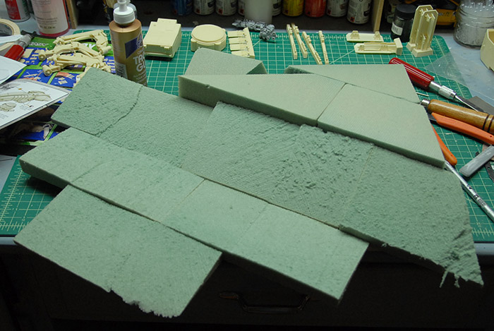
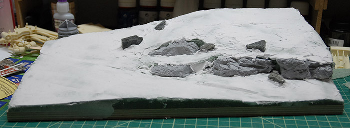
My idea was to have a road running through the scene, with a bit of a rocky hill next to it, separated by a guard rail. This meant I could have some interesting terrain, with both tanks in there, but separated a bit by both height and what they are standing on. I'm hoping to get a few figures in there as well, but that is for a later blog post. In order to get a base to work with, I just cut a piece if 1/2" plywood down to size and got myself a bunch of floral foam from the craft store. Below you can see it roughly cut and glued to the board.
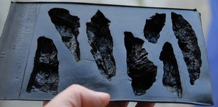
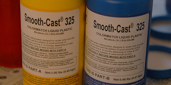
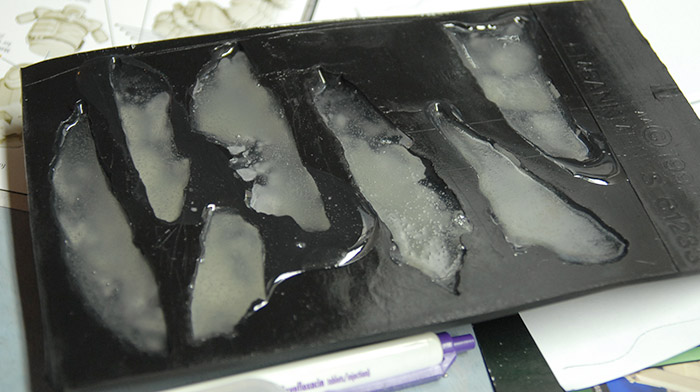
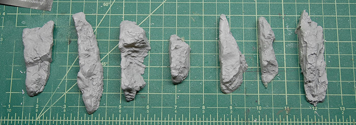
Next, I kicked around a few ideas for large rocks and was planning to use some stones I found outside, along with some sculpting, but then I ran across these rock molds when I was at one of my local hobby shops. The mold was only about $10, and I knew my wife had some two-part plastic resin at home that I could appropriate, so I bought the mold and decided to give it a try. Below you can see the mold, which I believe was intended for railroad decoration building.
First of the two is a heavy walking tank kit from MIG Productions, who are more commonly known for their pigments:
Along with that kit, I'll be building a more futuristic walking tank kit, the Rook, from Industria Mechanika:
Before I get into construction, let's compare and contrast the two kits. Industria Mechanika's kit consists of a very large number of parts (many of which are in the bags seen below), cast in an opaque grey resin. This is accompanied by a few pieces if brass rod, to be bent into grab handles and two sheets of photo-etch. It also includes two figures in the form of pilots that fit into the cockpit seats.
The casting quality is some of the best I've ever seen on a resin kit, with most of the parts having a small tab left on them, which doubles as part identification numbering. Generally, though, there are almost no large pour blocks on any of the parts. There are a few areas where a thin sheet of resin is left, that needs to be trimmed away, but I personally find this to be much easier than having to cut/sand a large block of resin away. The quality of the resin on this kit is very plastic-like, in that is is not too brittle and carves easily with an x-acto blade.
The MIG kit is cast from a tan resin, which is a bit more standard in cast resin parts. This kit is nearly all resin, with a bit of tubing for hydraulic hoses.
This resin is a bit more brittle than the grey resin seen above and has the more commonly found pour blocks, bubbles and need for a great deal of clean up. It also requires a good deal more shaping, drilling, etc in order to get it all to go together. Overall, though, the fidelity of the parts is still good. Below you can see some of the parts with their pour blocks still attached.
I decided to get started with the MIG model, beginning with the legs. I found that most of the leg length, on the outside, would eventually be covered by an armor plate, so I did a fairly rough clean up job. Below you can see the trimmed parts, with the various hinge holes drilled out.
These legs are held together by resin pins that go through the drilled out holes. Then, the leg position is held by hydraulics, part of which needs to be cut to length. This means that each leg consists of four main parts and a bunch of pins and cylinders that hold the big parts together. Below you can see the four legs with the pins in (not glued yet), but without any of the hydraulics.
Next, I put the hydraulics in place, but just kinda stuck on there, so that the legs were easily positionable. Then, using some museum tack, I stuck the legs onto the central body part, making sure that they all fit, etc. Below you can see it standing on it's own (although precariously, since nothing has been glued yet).
It was at this point that I realized that in order to be able to glue the legs into the correct positions, I'd need to know what they were standing on. This meant that I needed to stop the leg building and start figuring out what the diorama was going to look like. I decided on a rough base size, and then made myself some handy paper cutouts that were about the size of the finished tanks. In order to get an idea of the Rook kits size, I rubber-banded together one leg, stuck it to the body and guessed from there. Below you can see my two tank cutouts and my indication of where I wanted a road to be running. I got the width of the road by taking a standard two lane road with and dividing by 35, since the tanks are 1/35 scale.
My idea was to have a road running through the scene, with a bit of a rocky hill next to it, separated by a guard rail. This meant I could have some interesting terrain, with both tanks in there, but separated a bit by both height and what they are standing on. I'm hoping to get a few figures in there as well, but that is for a later blog post. In order to get a base to work with, I just cut a piece if 1/2" plywood down to size and got myself a bunch of floral foam from the craft store. Below you can see it roughly cut and glued to the board.
Next, I kicked around a few ideas for large rocks and was planning to use some stones I found outside, along with some sculpting, but then I ran across these rock molds when I was at one of my local hobby shops. The mold was only about $10, and I knew my wife had some two-part plastic resin at home that I could appropriate, so I bought the mold and decided to give it a try. Below you can see the mold, which I believe was intended for railroad decoration building.
Hornethopter Completion
18 - November - 2012 - 09:08
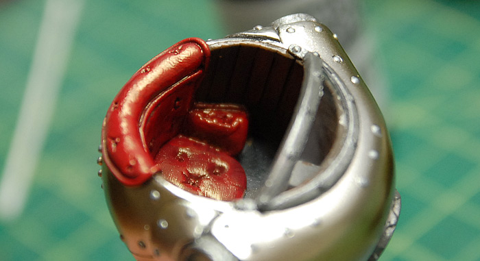
Painting continued on the Hornethopter. Once the exterior surfaces were generally complete, I moved on to the cockpit. I aimed to have a red velvet seat, wood panelling and misc metal and gray control surfaces. After I got most of it painted, I found that the red paint that I used had a bit more of a sheen than I had expected, and instead of a flat velvet-like red, it was more of a red leather. But, since I wasn't too married to the idea of red velvet and I actually like the way the red leather looked, I decided to just stick with that and leave it as-is.
At this point I was ready to start general assembly. Below you can see the two major structure parts joined together.
The catch was that I couldn't really do much more assembly until I could get the model up off of the ground, since the legs hang down and were likely to just get broken or scratched up if I attached them too early. With that in mind, I headed over to a local hardwood store and picked up a block of wood that was intended for turning on a latch. This meant that it came in large blocks, and was dipped in wax (presumably to keep it an even moisture level). I found a fairly small and inexpensive chunk that had a nice burl look to it and brought it home. It required cutting down a bit in order to get a proper sized piece as well as some quality time with a blow torch in order to melt off the bulk of the wax coating. So, with a hand saw/mitre box combo and lots of elbow grease, I ended up with the piece you see below.
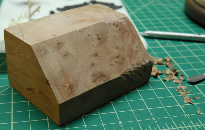
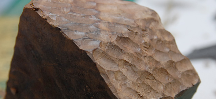
As you can see, the flat surfaces are a bit plain, and I wanted something that went with the steampunk theme a little better. I opted for a more organic hand-carved look for the block. This meant that I had to spend a bit of time going over the whole thing, breaking up the smooth surfaces and making it all look a bit more rustic.
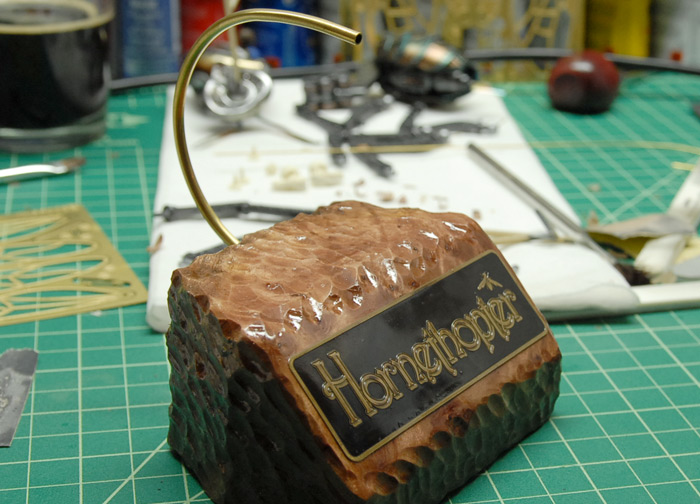
After that, the block spent some quality time with gloss polyurethane and a brush, getting it all nice and shiny. I painted the name plate black and then gave it a light sanding to bring the raised text out. It then got a few coats of spray clear and was mounted to the flat front of the block. Finally, I ran some 1/8" brass tubing through a tube bender to get it curved nicely and attached that to the block as well.
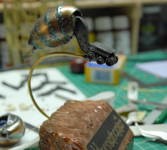
Below you can see the frame of the Hornethopter mounted to the base.
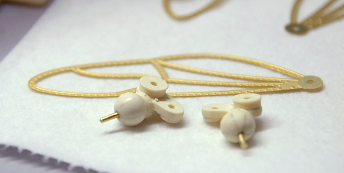
With that done, construction could precede, with the other parts being mounted and the wings finally being started on. I realized that it probably would have been a bit better to figure out the wing mounting techniques a bit earlier, before painting, since it was going to be tricky to not damage the paint now. I settled on a little trick that worked pretty well: I drilled holes into the wing sockets on the body of the model, and the set brass rod in there that was the exact depth of the hole. I put a tiny dab of super glue on the end of the rod and then pressed the wing base into the socket at the angle that I wanted it to stay at. This caused the bit of rod to stick to the wing in the exact spot and at the exact angle that I needed. I then gently removed both and drew a bunch of reference lines in pencil on the wing base. Then I could remove the brass rod and drill a hole at just the right angle to make it all fit back together perfectly (except stronger).
Below you can see the wing bases with their brass rods glued it, and with the reference marks still in place.
The wing frames after their coats of black gloss paint and a few coats of the same chrome paint that the rest of the body got.
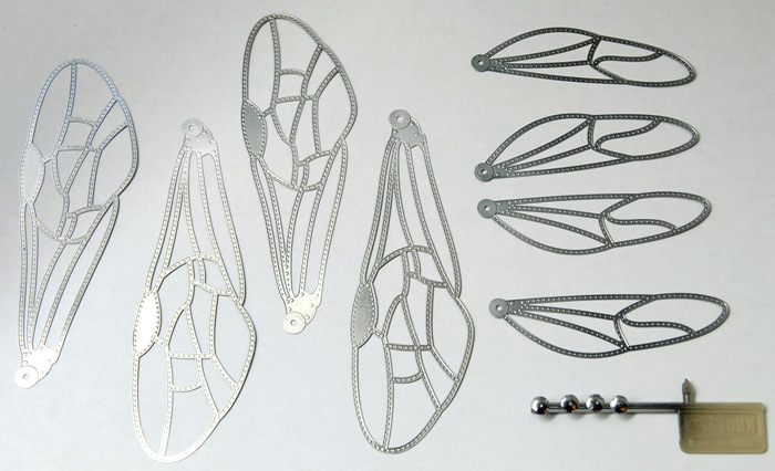
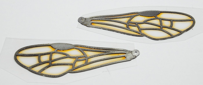
Using the wing template available from the manufacturer's web site, I designed some wing film inserts that had the same general color scheme as the rest of the model. These were printed out on ink-jet-friendly transparency film and glued in between the layers of photo-etch wing. Here you can see them before the excess was trimmed off.
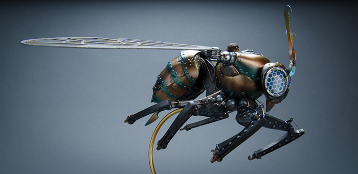
Finally, the wings were attached, any paint chips were touched up, and a little bit of grease/oil/rust was added here and there.
Click HERE or on the image below to see the galley of the completed model.
At this point I was ready to start general assembly. Below you can see the two major structure parts joined together.
The catch was that I couldn't really do much more assembly until I could get the model up off of the ground, since the legs hang down and were likely to just get broken or scratched up if I attached them too early. With that in mind, I headed over to a local hardwood store and picked up a block of wood that was intended for turning on a latch. This meant that it came in large blocks, and was dipped in wax (presumably to keep it an even moisture level). I found a fairly small and inexpensive chunk that had a nice burl look to it and brought it home. It required cutting down a bit in order to get a proper sized piece as well as some quality time with a blow torch in order to melt off the bulk of the wax coating. So, with a hand saw/mitre box combo and lots of elbow grease, I ended up with the piece you see below.
As you can see, the flat surfaces are a bit plain, and I wanted something that went with the steampunk theme a little better. I opted for a more organic hand-carved look for the block. This meant that I had to spend a bit of time going over the whole thing, breaking up the smooth surfaces and making it all look a bit more rustic.
After that, the block spent some quality time with gloss polyurethane and a brush, getting it all nice and shiny. I painted the name plate black and then gave it a light sanding to bring the raised text out. It then got a few coats of spray clear and was mounted to the flat front of the block. Finally, I ran some 1/8" brass tubing through a tube bender to get it curved nicely and attached that to the block as well.
Below you can see the frame of the Hornethopter mounted to the base.
With that done, construction could precede, with the other parts being mounted and the wings finally being started on. I realized that it probably would have been a bit better to figure out the wing mounting techniques a bit earlier, before painting, since it was going to be tricky to not damage the paint now. I settled on a little trick that worked pretty well: I drilled holes into the wing sockets on the body of the model, and the set brass rod in there that was the exact depth of the hole. I put a tiny dab of super glue on the end of the rod and then pressed the wing base into the socket at the angle that I wanted it to stay at. This caused the bit of rod to stick to the wing in the exact spot and at the exact angle that I needed. I then gently removed both and drew a bunch of reference lines in pencil on the wing base. Then I could remove the brass rod and drill a hole at just the right angle to make it all fit back together perfectly (except stronger).
Below you can see the wing bases with their brass rods glued it, and with the reference marks still in place.
The wing frames after their coats of black gloss paint and a few coats of the same chrome paint that the rest of the body got.
Using the wing template available from the manufacturer's web site, I designed some wing film inserts that had the same general color scheme as the rest of the model. These were printed out on ink-jet-friendly transparency film and glued in between the layers of photo-etch wing. Here you can see them before the excess was trimmed off.
Finally, the wings were attached, any paint chips were touched up, and a little bit of grease/oil/rust was added here and there.
Click HERE or on the image below to see the galley of the completed model.
Hornethopter Painting
25 - September - 2012 - 20:42
Hi there! Just a quick post today to show a bit of progress on the painting of the Hornethopter. In the last post, I showed my inspiration sheet, with the heat-treated titanium images on it. Also shown were the various parts that had been sprayed with the chrome paint. This post aims to show a few of the steps in going from chrome to heat-treated.
I switched the airbrush to the super-fine tip and needle and loaded it up with just a tiny bit of diluted Tamiya clear yellow. With the pressure set to about 15-20lbs, I freehanded some soft bands of yellow across the abdomen sections. Once I had bands of yellow on all the parts, I followed up with similarly-diluted clear red. Soft bands of clear red gave me something like so:
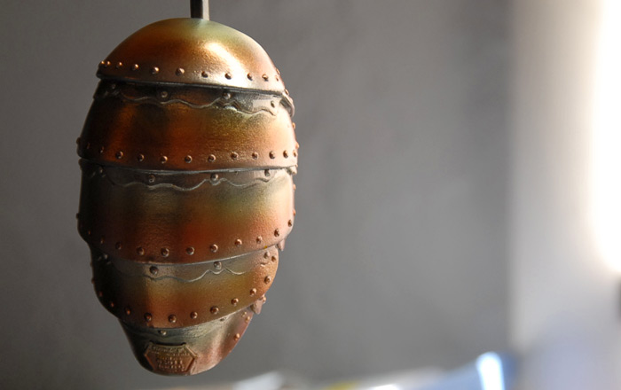
Below you can see the yellow and red in place and the part masked before applying the clear blue.
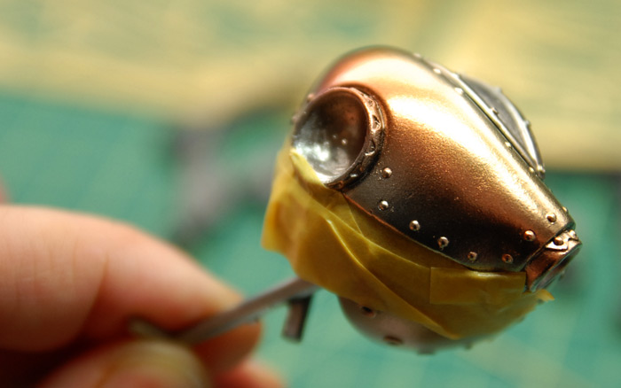
And the abdomen masked and painted with the first pass of blue:
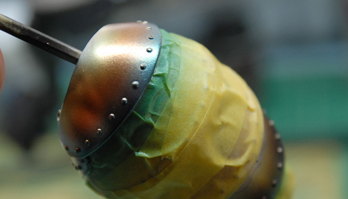
Thorax fully sprayed with all three colors:
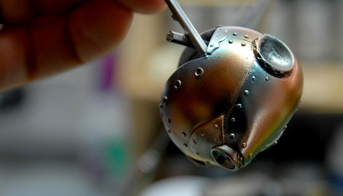
The abdomen was tricky, because it had to be painted in three steps. This was required in order to give each section plenty of space to blend the blue in, but still get a clean line against the section below. Below you can see the abdomen with all three colors applied.
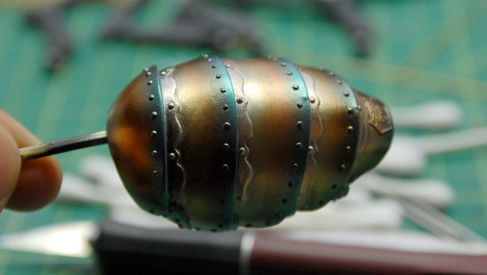
Next up is putting a contrasting dark steel color on the filigree-like metal strips between the sections as well as the casting plate right at the tail. That will be following by the beginning of hand painting the cockpit and picking out all the rivets with a contrasting paint. Thanks for reading!
I switched the airbrush to the super-fine tip and needle and loaded it up with just a tiny bit of diluted Tamiya clear yellow. With the pressure set to about 15-20lbs, I freehanded some soft bands of yellow across the abdomen sections. Once I had bands of yellow on all the parts, I followed up with similarly-diluted clear red. Soft bands of clear red gave me something like so:
Below you can see the yellow and red in place and the part masked before applying the clear blue.
And the abdomen masked and painted with the first pass of blue:
Thorax fully sprayed with all three colors:
The abdomen was tricky, because it had to be painted in three steps. This was required in order to give each section plenty of space to blend the blue in, but still get a clean line against the section below. Below you can see the abdomen with all three colors applied.
Next up is putting a contrasting dark steel color on the filigree-like metal strips between the sections as well as the casting plate right at the tail. That will be following by the beginning of hand painting the cockpit and picking out all the rivets with a contrasting paint. Thanks for reading!
Hornethopter Continued
09 - September - 2012 - 20:00
I should never have claimed that the build was moving quickly and wouldn't take very long, as that pretty much ensured that it would grind to a halt almost instantly.
So, the problem that I had with this one was that I didn't have a clear idea of exactly how I was going to paint and mount it. I hit the point where I needed to start assembly and drilling/pinning parts together, but I didn't have a mental picture of how the legs should be posed. After stewing on it for a few weeks I finally just started searching the interwebs for inspiration. I really liked the ideas of having some of the parts look like heat-treated titanium. I also wanted to embrace some of the kits steam punk look while also incorporating some modern military cues and some elements from real wasps. At the same time I did't want to repeat what I had already seen online, but I wanted to draw some inspiration from good looking models that others had built.
With all that in mind, I collected images, put them all together into a 13" x 19" format and printed myself out a big ol inspiration sheet. Below is the fun-sized internet version. Please note that this is a collection of other peoples photos, so the copyrights generally belong to them, so hopefully they won't sue me or anything ;)
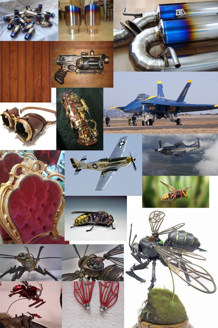
Also, I have recently purchased quite a few new paints (mentioned in a previous post), but didn't really have a good way to organize them. I was finding that these taller skinny bottle were just lurking about my model desk in a group, often falling over, and generally being difficult to deal with. It was hard to quickly find the color that I wanted and it was easy to bump them so they all fell over. After a bit of consideration, I decided it was time to build a new little paint shelf, better suited to my new model desk and the differently-sized bottles. On my way home from work, I swung by Home Depot, picked up a $5 sheet of 1/4" thick MDF board and got to work. I settled on a shelf that was about 4ft long and about 7.5" tall, and 4" deep. I just sketched it out quickly, marked the board and cut out a bunch of pieces. I then realized I had cut the slot in two of the upright parts in the wrong place and called it a day ;)
The next day, I cut two new parts and glued the whole thing together. Below you can see the end result, putting most of my paints and pigments within arms reach.
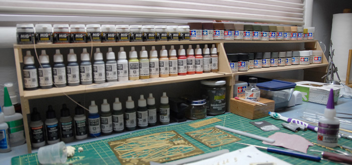
With some inspiration gained, and the model desk freshly organized, I began gluing things together. Below you can see the legs put together. I glued the upper and lower sections together first and then drilled through the joint with a pin vice and glued some brass rod into the hole in order to strengthen the joint. The leg pose that I decided on was one that hopefully mimics the legs of a real hornet, when in flight. The image above of the flying hornet is what I was aiming for. While I can't hit the pose exactly, since the kit legs can't fold up against the body quite that far, I'm hoping that the general feel will be similar.
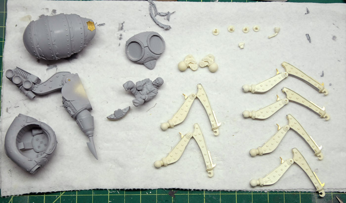
With a coat of primer sprayed onto these parts, I began the rough assembly. This consisted of marking, taping and sticking (with museum tack) the various parts together, so that I could drill holes and glue in brass pins where needed. The legs, for example, were posed and then held by one hand, while the other hand used the Dremel (with the flexi-wand attachment thing), fitted with a tiny drill bit, to drill through the ball joint into the body. Then, I could fit an appropriately-sized length of brass rod through this hole. I glued the rod just to the leg, making it so I could take the whole thing apart, but once painting is done, it can be easily reassembled just as intended. Below you can see the first three legs pinned in place.
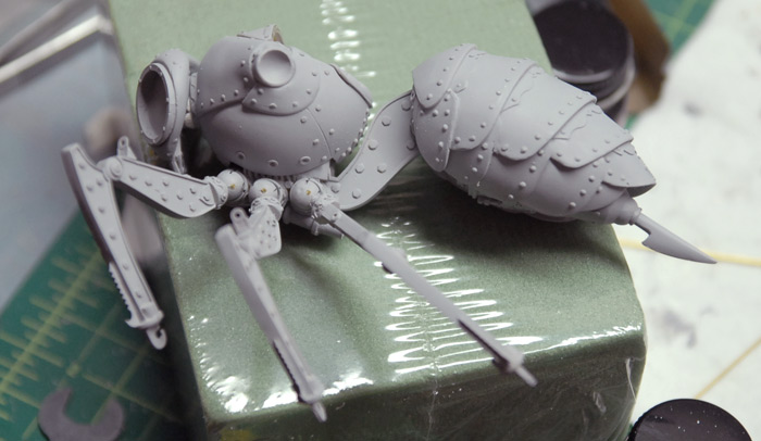
Once I had all the pins installed in the legs, I prepped all of the sprayable parts for painting by attaching various handles to them.
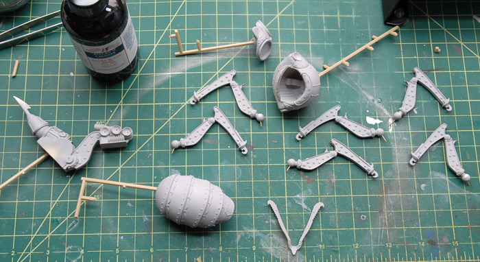
As I alluded to earlier, I decided to go with a metal finish for most of the model. I decided to use Alclad lacquer on this model, which is not something I have tried before. For the finishes I am using, it is a two step process. First, a gloss black paint is sprayed over the parts, and then, after drying for a day, the metallic paint is lightly sprayed over the black. Below you can see the legs with their gloss black coat.
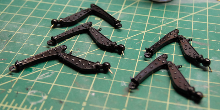
The abdomen with its gloss black:
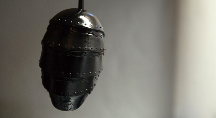
For the legs and connecting frame, I used Alclad Steel paint, which is a darker, semi-gloss finish. Below you can see the legs hanging to dry.
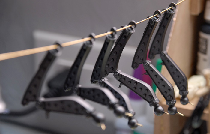
The rest of the parts were painted with Alclad Chrome. This is a nice bright, high-gloss paint, although a bit trickier to apply well than the steel color was. The plans is to get these parts nice and bright and then go back over them with a few colors of clear yellow, red and blue paint, hopefully getting the rainbow looks of heat treated titanium. Depending on how that turns out, I may then dull it all down a bit with some weathering and dirt, but I'll play that by ear.
Below is the thorax drying.
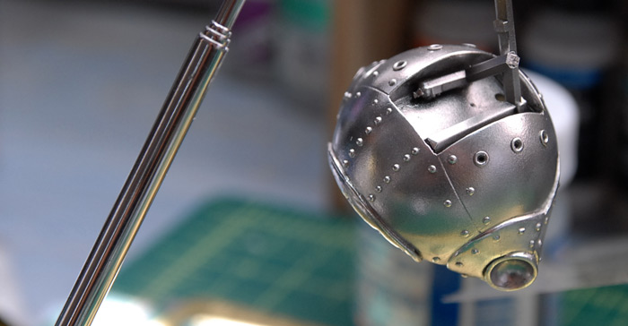
And the abdomen after its chrome treatment. This one ended up with a few duller areas, and may need another coat to even it out.
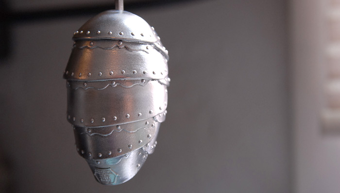
Below you can see the main connecting structure painted in steel, with the stinger painted chrome.
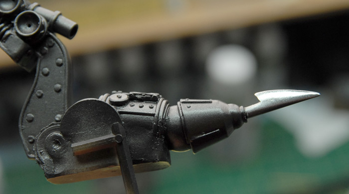
That's where I am as of this evening. Next up is a bit of repainting on the abdomen and then a shot at the multi-color clear treatment. Also, as soon as the cockpit section is done with airbrushing, I can begin hand painting the wood and seat in there as well as the pilot and control panel.
So, the problem that I had with this one was that I didn't have a clear idea of exactly how I was going to paint and mount it. I hit the point where I needed to start assembly and drilling/pinning parts together, but I didn't have a mental picture of how the legs should be posed. After stewing on it for a few weeks I finally just started searching the interwebs for inspiration. I really liked the ideas of having some of the parts look like heat-treated titanium. I also wanted to embrace some of the kits steam punk look while also incorporating some modern military cues and some elements from real wasps. At the same time I did't want to repeat what I had already seen online, but I wanted to draw some inspiration from good looking models that others had built.
With all that in mind, I collected images, put them all together into a 13" x 19" format and printed myself out a big ol inspiration sheet. Below is the fun-sized internet version. Please note that this is a collection of other peoples photos, so the copyrights generally belong to them, so hopefully they won't sue me or anything ;)
Also, I have recently purchased quite a few new paints (mentioned in a previous post), but didn't really have a good way to organize them. I was finding that these taller skinny bottle were just lurking about my model desk in a group, often falling over, and generally being difficult to deal with. It was hard to quickly find the color that I wanted and it was easy to bump them so they all fell over. After a bit of consideration, I decided it was time to build a new little paint shelf, better suited to my new model desk and the differently-sized bottles. On my way home from work, I swung by Home Depot, picked up a $5 sheet of 1/4" thick MDF board and got to work. I settled on a shelf that was about 4ft long and about 7.5" tall, and 4" deep. I just sketched it out quickly, marked the board and cut out a bunch of pieces. I then realized I had cut the slot in two of the upright parts in the wrong place and called it a day ;)
The next day, I cut two new parts and glued the whole thing together. Below you can see the end result, putting most of my paints and pigments within arms reach.
With some inspiration gained, and the model desk freshly organized, I began gluing things together. Below you can see the legs put together. I glued the upper and lower sections together first and then drilled through the joint with a pin vice and glued some brass rod into the hole in order to strengthen the joint. The leg pose that I decided on was one that hopefully mimics the legs of a real hornet, when in flight. The image above of the flying hornet is what I was aiming for. While I can't hit the pose exactly, since the kit legs can't fold up against the body quite that far, I'm hoping that the general feel will be similar.
With a coat of primer sprayed onto these parts, I began the rough assembly. This consisted of marking, taping and sticking (with museum tack) the various parts together, so that I could drill holes and glue in brass pins where needed. The legs, for example, were posed and then held by one hand, while the other hand used the Dremel (with the flexi-wand attachment thing), fitted with a tiny drill bit, to drill through the ball joint into the body. Then, I could fit an appropriately-sized length of brass rod through this hole. I glued the rod just to the leg, making it so I could take the whole thing apart, but once painting is done, it can be easily reassembled just as intended. Below you can see the first three legs pinned in place.
Once I had all the pins installed in the legs, I prepped all of the sprayable parts for painting by attaching various handles to them.
As I alluded to earlier, I decided to go with a metal finish for most of the model. I decided to use Alclad lacquer on this model, which is not something I have tried before. For the finishes I am using, it is a two step process. First, a gloss black paint is sprayed over the parts, and then, after drying for a day, the metallic paint is lightly sprayed over the black. Below you can see the legs with their gloss black coat.
The abdomen with its gloss black:
For the legs and connecting frame, I used Alclad Steel paint, which is a darker, semi-gloss finish. Below you can see the legs hanging to dry.
The rest of the parts were painted with Alclad Chrome. This is a nice bright, high-gloss paint, although a bit trickier to apply well than the steel color was. The plans is to get these parts nice and bright and then go back over them with a few colors of clear yellow, red and blue paint, hopefully getting the rainbow looks of heat treated titanium. Depending on how that turns out, I may then dull it all down a bit with some weathering and dirt, but I'll play that by ear.
Below is the thorax drying.
And the abdomen after its chrome treatment. This one ended up with a few duller areas, and may need another coat to even it out.
Below you can see the main connecting structure painted in steel, with the stinger painted chrome.
That's where I am as of this evening. Next up is a bit of repainting on the abdomen and then a shot at the multi-color clear treatment. Also, as soon as the cockpit section is done with airbrushing, I can begin hand painting the wood and seat in there as well as the pilot and control panel.
Next Up: Hornethopter
14 - July - 2012 - 19:23
Moving right along, I've decided to try something new for my next project. While I worked with resin castings a bit during the Panzer build, I have never done a full resin model before. A little while back, my good friend, Neil Blevins, pointed me towards the Industria Mechanika web site. Industria Mechanika does both resin kit design as well as coordinating other artists and their designs. They bring the designs together with the production means and end up selling limited-run resin kits in a variety of themes. Finding their designs, and the premise of trying out a resin kit, interesting, I ordered up one of the smaller kits just as they were running the third edition of it.
That brings me to the next model:
This one is a steampunk-styled Hornet-shaped ornithopter.
As you can see below, this kit is mostly resin castings, but also has a few photo-etch sheets (which are impressively thick), a clear windshield and two glass eye lenses. It also comes with a bit of coated wire for the leg rigging, but I don't think it i visible in the image below.
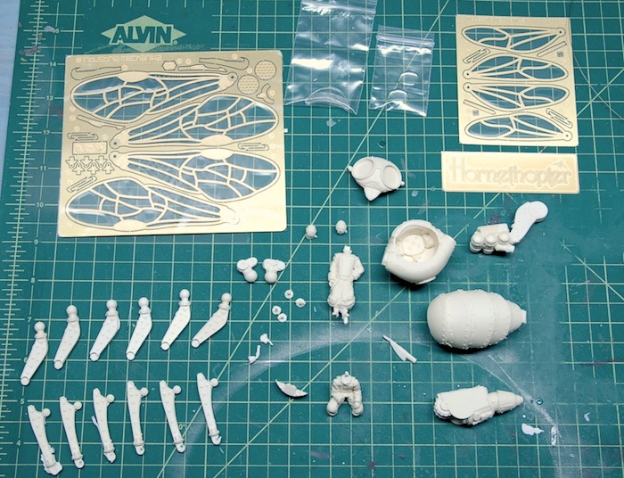
Here is a close-up on the straight-from-the-box leg segments. These will require a bit of clean up, a bit of filling and things of that nature, but overall, the castings look good and have lots of detail.
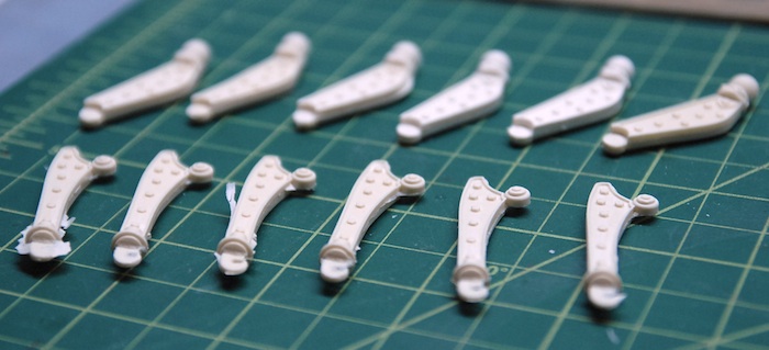
Below, you can see the main parts of the wasp body and the bodies of the figures that come with the kit.
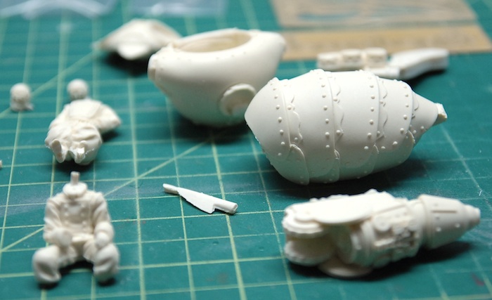
This build is moving fairly quickly, since the overall parts count is much lower than the average plastic model. I expect to complete this one within a month or so, so watch out for more updates!
That brings me to the next model:
This one is a steampunk-styled Hornet-shaped ornithopter.
As you can see below, this kit is mostly resin castings, but also has a few photo-etch sheets (which are impressively thick), a clear windshield and two glass eye lenses. It also comes with a bit of coated wire for the leg rigging, but I don't think it i visible in the image below.
Here is a close-up on the straight-from-the-box leg segments. These will require a bit of clean up, a bit of filling and things of that nature, but overall, the castings look good and have lots of detail.
Below, you can see the main parts of the wasp body and the bodies of the figures that come with the kit.
This build is moving fairly quickly, since the overall parts count is much lower than the average plastic model. I expect to complete this one within a month or so, so watch out for more updates!
Looooooong Overdue Update...
19 - June - 2010 - 07:28
So, yes, I realize I became one of those people that starts up a blog with all the intentions of keeping it updated, and then fell behind. But now I'm back and I've got a bunch of updates!
First and foremost, I've finished the Panzer III and have some photos of the finished project. I forgot to take photos of the outside, as I was putting everything together, so I really just have the images of the finished model. Everything on the outside was pretty straight forward, without all the complicated resin construction that the interior had.
The difficult bits of the exterior were really just the assembly of the individual-link plastic tracks and then the final assembly and weathering of the whole tank. I managed to get the tracks assembled by sticking the track links to a strip of thin masking tape, then draping that over the various wheels, and once in place, dabbing glue to where the tracks touch one another. I found that I could make each side in four or so sections, which still allowed me to take the tracks back off, paint them, and then, once the rest of the tank was painted, put the tracks back on again.
The painting was simply an airbrushed coat of dark yellow on most of the exterior, with a few of the detail parts picked out in other colors by hand. The road wheels were originally painted in German Grey, and then, using a plastic circle template as a mask, the centers were sprayed the same dark yellow as the rest of the tank. After the base coats were complete, I sprayed a slightly darker yellow into the nooks, crannies and corners to get a bit of shading. This was followed by a pass of drybrushing with a light tan to help pick out corners, details and texture.
Next came an extensive application of Mig Pigments. These are just colored powders, that get dusted onto the surface and then a bit of thinner is touched to the powder, and that helps it stick to the surface and flow into the texture of the surface and in between details. This serves to both further pick out detail when using a darker color pigment, and also to add dirt and grime when using lighter tones.
Once that was done, I cut a chunk of red oak for a base, put a few coats polyurethane on that and called it done! Since then, I have grown less happy with the base, feeling that it needed to better contrast with the model, so stay tuned for an update on that.
Here are a few images of the completed model, but see the completed models section of this web site for more.
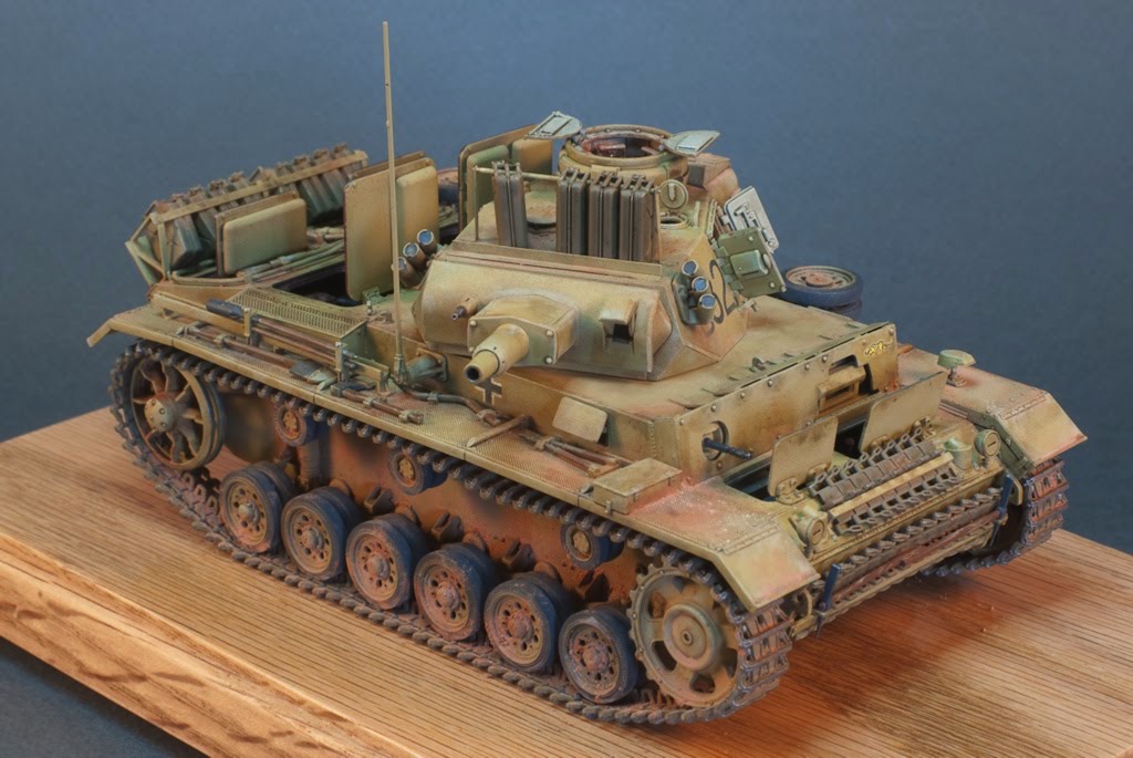
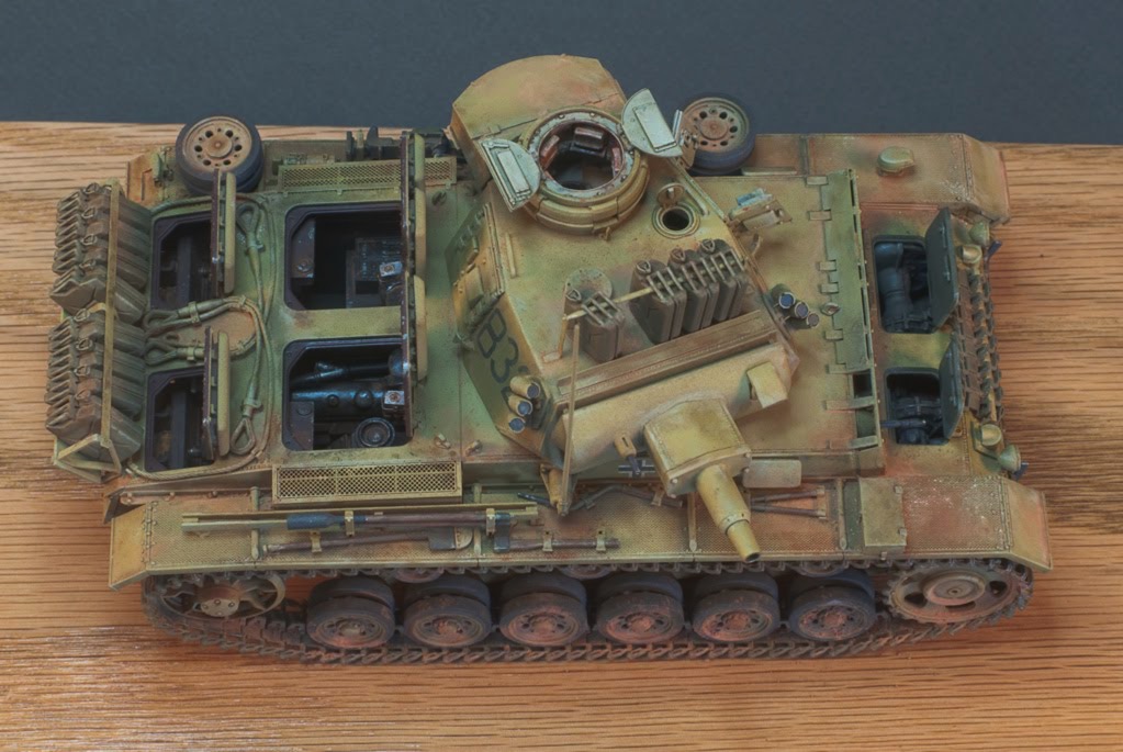
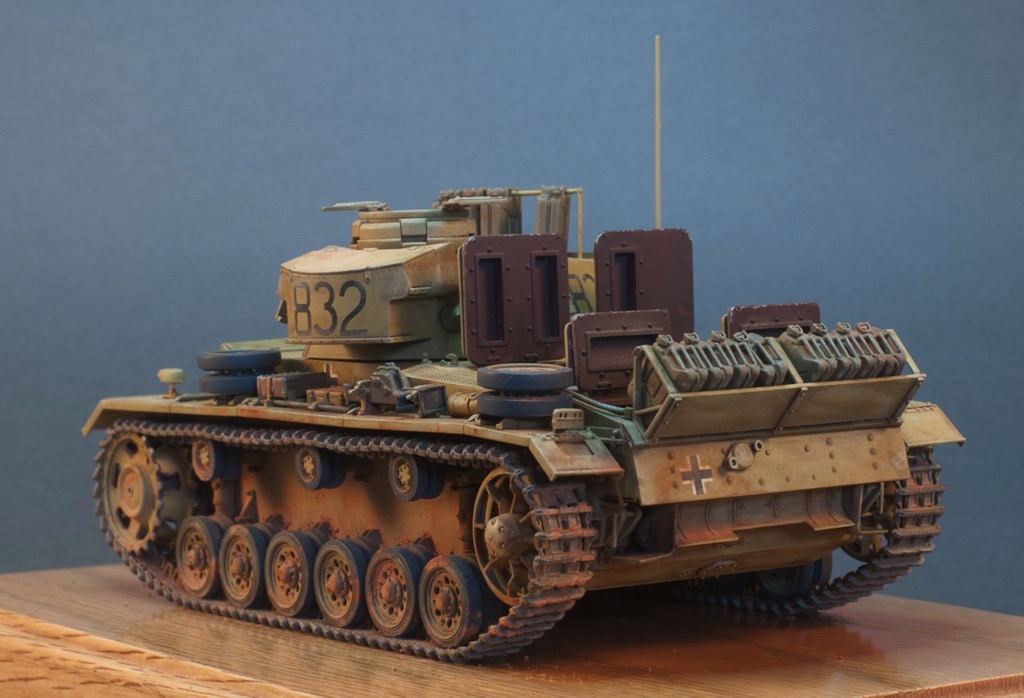
Panzer III Interior Paint
13 - February - 2010 - 09:10
With the interior build pretty much complete, I moved on to added a bit of paint. From what I could gather, the Germans painted everything in a red primer and left it that way for non-crew areas and painted all the crew areas in a dull grey-green.
I began by airbrushing the whole interior with Mr Surfacer 1200 as a primer and to give it all a uniform color. Next I sprayed the red-brown color onto the engine compartment and onto the engine and radiator assemblies. I decided to leave the engine and radiator parts separate during the painting and weathering process to make things easier. Finally, I masked the engine area and sprayed the crew cabin in the grey green.
Next I spent a bit of time picking out a few details by hand and adding metallic spots on corners to simulate paint chips. Here you can see a little of that in progress:
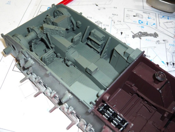
I followed that with a bit of dry brushing using a lighter tone to help pick out the details and raised bits. Next I tried out a technique that is new to me: the use of pigments. Pigment is the raw color component of many paints (although in a non-toxic version). I ordered a few sets of Mig Pigments from an online hobby store (since I have never seen more than a few jars locally), and now I've got 12 shades of rust, dirt, smoke and ash to choose from.
The jist of the pigments is that you sort of just use a dry brush to apply a variety of colors here and there, and then wet everything down with a thinner and use that to blend between colors and get the solution into all the cracks and crevices. I started out with a wash of black to help add contrast and pick out the details, and then followed up with various dirt and rust colors. I generally found it very easy to work with and I am quite pleased with the results.
A few images of paint and weathering (with the pigments):
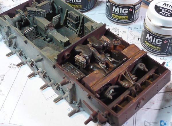
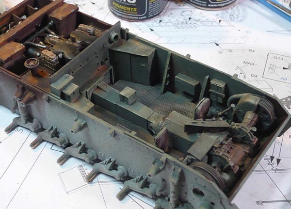
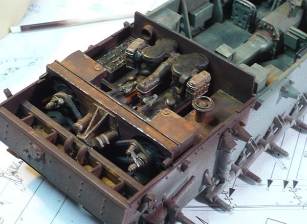
That pretty much wraps up the interior. There are a few odds and ends to take care of, like cementing the engine parts in place and connecting a few things with pipes. I'm sure there will also be a bit of work going into the upper hull build as well, but that is all for a later post.
Next: Onward with the construction!
I began by airbrushing the whole interior with Mr Surfacer 1200 as a primer and to give it all a uniform color. Next I sprayed the red-brown color onto the engine compartment and onto the engine and radiator assemblies. I decided to leave the engine and radiator parts separate during the painting and weathering process to make things easier. Finally, I masked the engine area and sprayed the crew cabin in the grey green.
Next I spent a bit of time picking out a few details by hand and adding metallic spots on corners to simulate paint chips. Here you can see a little of that in progress:
I followed that with a bit of dry brushing using a lighter tone to help pick out the details and raised bits. Next I tried out a technique that is new to me: the use of pigments. Pigment is the raw color component of many paints (although in a non-toxic version). I ordered a few sets of Mig Pigments from an online hobby store (since I have never seen more than a few jars locally), and now I've got 12 shades of rust, dirt, smoke and ash to choose from.
The jist of the pigments is that you sort of just use a dry brush to apply a variety of colors here and there, and then wet everything down with a thinner and use that to blend between colors and get the solution into all the cracks and crevices. I started out with a wash of black to help add contrast and pick out the details, and then followed up with various dirt and rust colors. I generally found it very easy to work with and I am quite pleased with the results.
A few images of paint and weathering (with the pigments):
That pretty much wraps up the interior. There are a few odds and ends to take care of, like cementing the engine parts in place and connecting a few things with pipes. I'm sure there will also be a bit of work going into the upper hull build as well, but that is all for a later post.
Next: Onward with the construction!
Panzer III Interior Build
13 - February - 2010 - 08:50
So, it's been quite a while since I've updated so I've going to break this into two posts: one on the build and one about painting and weathering. First, the build:
I purchased resin interior and engine kits made by Verlinden. The interior kit was designed for a Tamiya version of the same tank, while the engine claimed it would fit both Tamiya and Dragon kits. When I got in there and slowly started piecing things together I discovered a few things:
First off, I'm not that crazy about working with large resin parts. There seems to be a ton of work to do just to get the part somewhere close to where it should be, since one needs to sand off a great deal of the overpour. There also seems to be a tendency of the large flat resin parts to warp a bit with the heat of sanding. I suppose these are things to learn about working with resin, and they will inform my future projects, but I just came away with the impression that resin is just plain less fun to work with compared to plastic or wood.
Next thing I learned was that the Tamiya version of the kit must not have all of the interior suspension parts that the Dragon kit does, as the resin parts had all of the same part cast into the floor of the interior. This gave me two options: cut away all the Dragon interior parts or cut away the resin parts. Since I thought the kit parts looked better than the resin parts, I opted for what was probably the hardest route, and decided to cut away the whole floor of the resin parts and replace it with a new version.
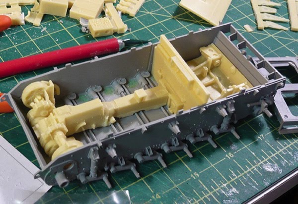
In retrospect, a closer inspection of some reference photos could have saved me some trouble. I started with the impression that the floor inside the tank was a metal mesh, similar to what one would find on catwalks and other industrial settings. So I cut away all the floor, and found some fine screen, with the intention of using the screen for the floor to simulate the grating. This would allow the fancy suspension bit to be seen through the floor just a little bit. Later on, in my quest for find proper paint colors, I ran across some photos of a restored Panzer and it had flooring made of diamond plate, which is quite opaque. So, instead of the screen idea and instead of trying to find some scale diamond plate, I took some styrene sheet, heated it with a cooking torch (like for making creme brulee) and pressed the screen from a cooking splatter guard into it to form a criss-cross pattern that is similar to diamond plate.
Finally, I learned that the interior and engine kits both came with a firewall to go between. Once all the parts for the interior and exterior are in place, without any firewalls, they take up pretty much the whole interior, leaving not enough room for EITHER firewall. So, what I ended up having to do is to build a new firewall from scratch from styrene. I tried to get the general shape from both of the resin parts and even clipped off a few of the resin details and added them to the new version. I also found that I had to cut quite a bit off of the bottom of the engine in order to get it to sit low enough in the chassis for the upper hull pieces to be able to attach. This, of course, caused all the pipes to mis-align, so there are still a few things that will need tweaking once paint is done and I am cementing things into the hull.
Some images of the built-up interior and engine:
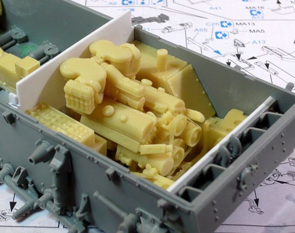
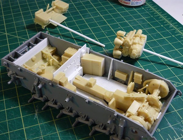
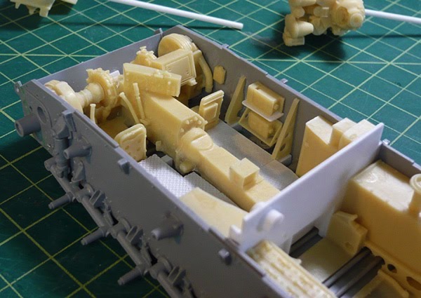
And finally, with a coat of Mr Surfacer 1200 as a primer:
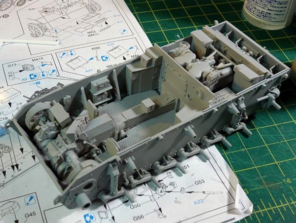
Next: some paint!
I purchased resin interior and engine kits made by Verlinden. The interior kit was designed for a Tamiya version of the same tank, while the engine claimed it would fit both Tamiya and Dragon kits. When I got in there and slowly started piecing things together I discovered a few things:
First off, I'm not that crazy about working with large resin parts. There seems to be a ton of work to do just to get the part somewhere close to where it should be, since one needs to sand off a great deal of the overpour. There also seems to be a tendency of the large flat resin parts to warp a bit with the heat of sanding. I suppose these are things to learn about working with resin, and they will inform my future projects, but I just came away with the impression that resin is just plain less fun to work with compared to plastic or wood.
Next thing I learned was that the Tamiya version of the kit must not have all of the interior suspension parts that the Dragon kit does, as the resin parts had all of the same part cast into the floor of the interior. This gave me two options: cut away all the Dragon interior parts or cut away the resin parts. Since I thought the kit parts looked better than the resin parts, I opted for what was probably the hardest route, and decided to cut away the whole floor of the resin parts and replace it with a new version.
In retrospect, a closer inspection of some reference photos could have saved me some trouble. I started with the impression that the floor inside the tank was a metal mesh, similar to what one would find on catwalks and other industrial settings. So I cut away all the floor, and found some fine screen, with the intention of using the screen for the floor to simulate the grating. This would allow the fancy suspension bit to be seen through the floor just a little bit. Later on, in my quest for find proper paint colors, I ran across some photos of a restored Panzer and it had flooring made of diamond plate, which is quite opaque. So, instead of the screen idea and instead of trying to find some scale diamond plate, I took some styrene sheet, heated it with a cooking torch (like for making creme brulee) and pressed the screen from a cooking splatter guard into it to form a criss-cross pattern that is similar to diamond plate.
Finally, I learned that the interior and engine kits both came with a firewall to go between. Once all the parts for the interior and exterior are in place, without any firewalls, they take up pretty much the whole interior, leaving not enough room for EITHER firewall. So, what I ended up having to do is to build a new firewall from scratch from styrene. I tried to get the general shape from both of the resin parts and even clipped off a few of the resin details and added them to the new version. I also found that I had to cut quite a bit off of the bottom of the engine in order to get it to sit low enough in the chassis for the upper hull pieces to be able to attach. This, of course, caused all the pipes to mis-align, so there are still a few things that will need tweaking once paint is done and I am cementing things into the hull.
Some images of the built-up interior and engine:
And finally, with a coat of Mr Surfacer 1200 as a primer:
Next: some paint!
Next Project! Dragon Panzer III Ausf.N Tank
13 - December - 2009 - 20:21
And now for something completely different...
So, I've begun my next project. I picked a few plastic armor kits up last February, when I stumbled upon a new hobby shop (which has since become my main hobby shop), and found that they were having a sale. I had done a little bit of reading and looked for kits that came with individual-link tracks, and some photo-etched metal parts, in hopes of finding the kits challenging. The one that I am starting with is a German Panzer tank, of a fairly late revision, with markings from their African campaign. This kit is made by Dragon, and they look to have gone above and beyond when it comes to the quality of the plastic molding and overall level of detail.
I've also decided to try quite a few new things on this project. Since I haven't really done any sort of armor model since I was a little kid, I figured I could try lots of new things, based on recent reading and get much of the learning going all at once. First off, I am trying some new paints, primers, and glues. I've picked up some Mr Surfacer products for priming and filling, some Pro Weld plastic welder to replace the Testors cement I've always used, some Milliput epoxy putty, and various super glues, sanding devices, etc, all that I have not tried before. Later in the project, I also hope to experiment with some new airbrushing techniques, and to try out some weathering techniques using pigments and some artist oils.
Here is the kit that I am working with.
Here's an example of the instructions. They don't seem to be real big on the step-by-step sort of approach and instead seem to go for more of a put-all-this-stuff-together-at-once sorta thing.
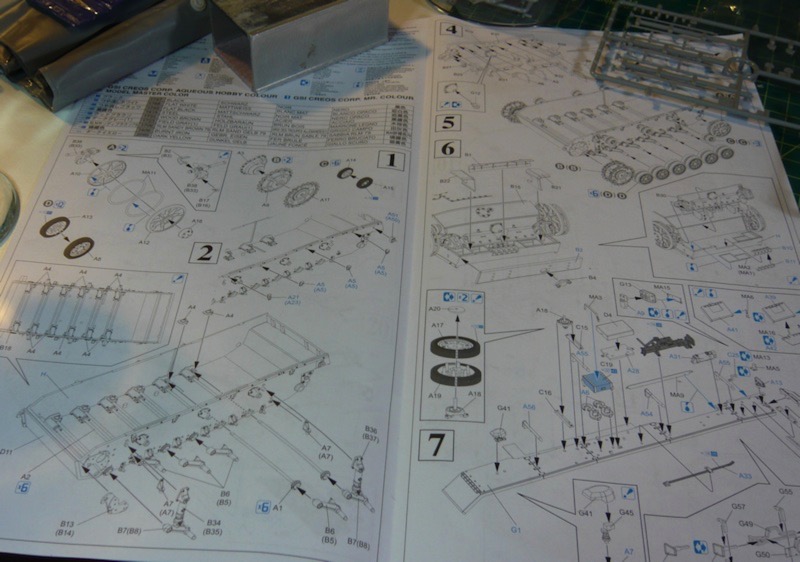
I've started putting a few pieces together. Mostly this has just involved a great deal of sanding and a little filling. I've been trying out filling tiny seams with Mr Surfacer 500, which is somewhere in between primer and filler. It seems to be working pretty well so far, although I've only used it to smooth over some seams on the drive wheels.
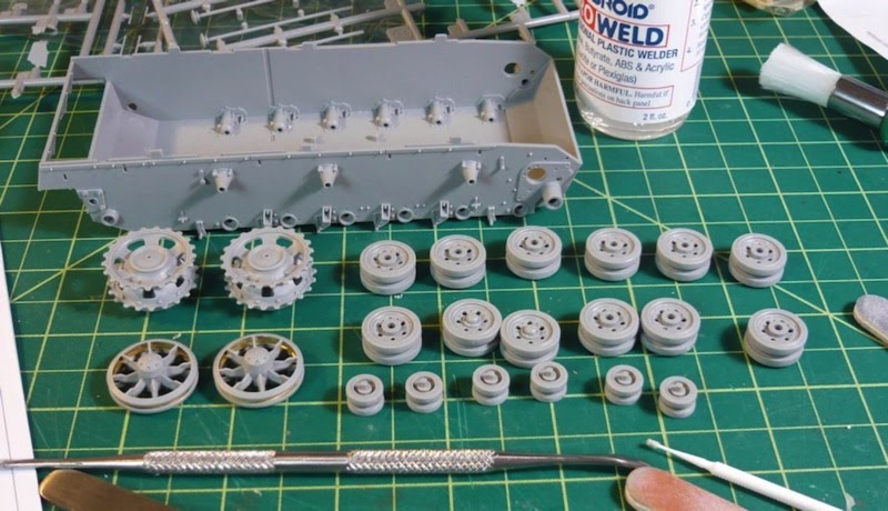
Another in the list of new things I am trying on this kit is the addition of a third-party resin interior kit. The model did not come with any interior parts beyond a few gun parts that go inside the turret. But, the kit DOES allow for all of the hatches and portals to be assembled in an open position. So, with a little scrounging and some sanity checks on the Fine Scale Modeler forums, I decided on an interior kit and an engine bay kit, both from Verlinden. The interior kit adds the various crew-related parts as well as a floor, transmission tunnel and various other transmission parts. The engine bay adds the bits on the other side of the firewall, which is mostly just the engine and some fans and things.
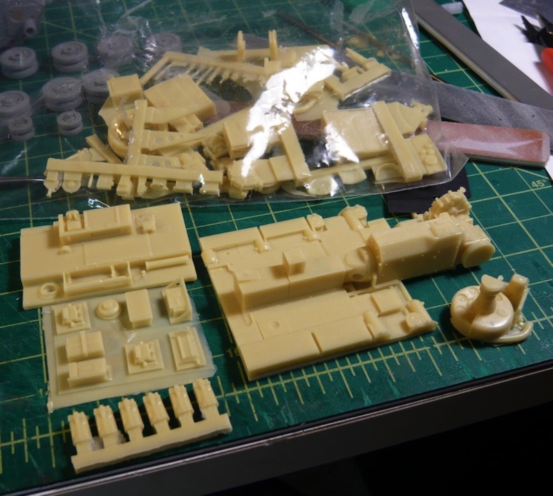
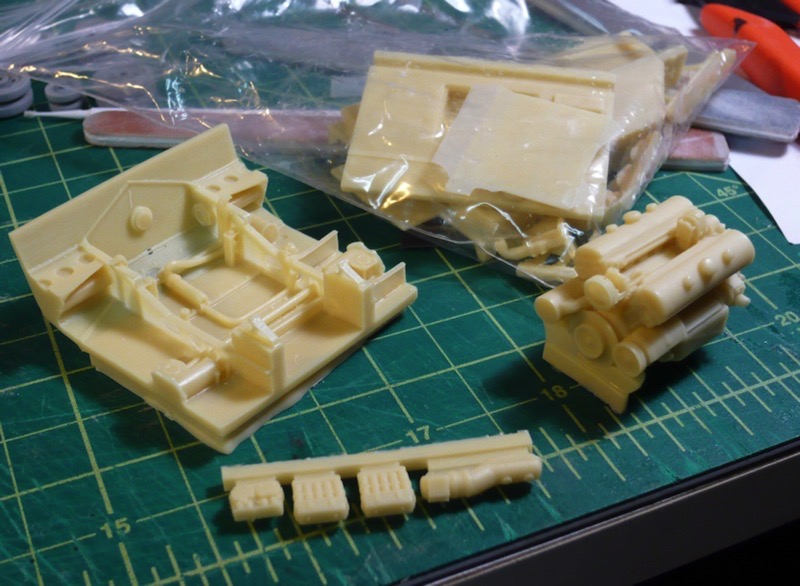
Here is how they roughly fit into the lower hull piece.
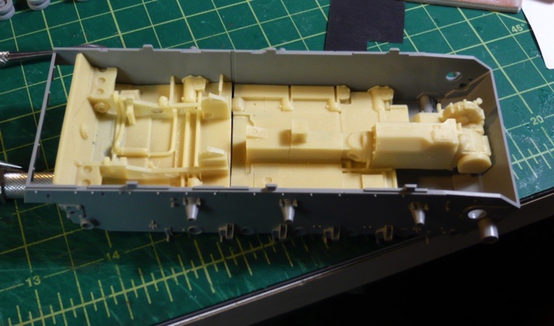
The big catch here, is that these resin bits were not made for this Dragon kit, but rather for a Tamiya kit, which has less internal detail. As a result, there is some duplication in details between the lower hull part of the plastic kit and the detail in the resin kit. This means that this will take a bit of figuring and some quality time with the Dremel in order to get everything to play nicely with one another. Below is an image, with tiny red arrows, illustrating the duplicated details.
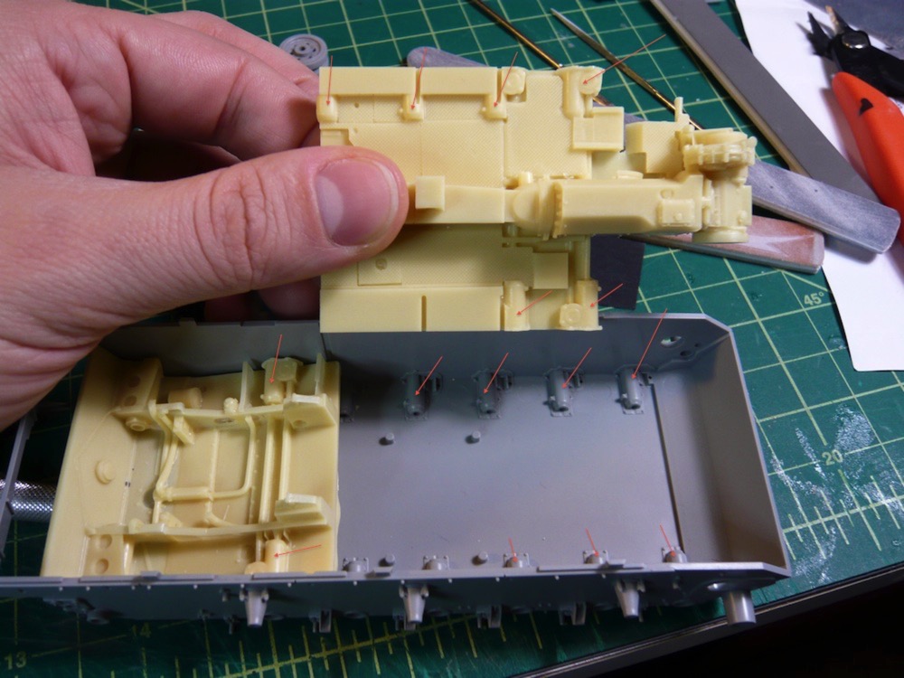
All in all, I am pretty excited about this project, as it is really nice to have a bit of a change of pace after all that time with wood and string and superglue. Stay tuned for further updates as this one progresses, hopefully at a slightly faster pace than the last project. If all goes well, I'm hoping to have this one completed in time to enter into the Hobby Expo 2010 on February 20th, in Petaluma.
So, I've begun my next project. I picked a few plastic armor kits up last February, when I stumbled upon a new hobby shop (which has since become my main hobby shop), and found that they were having a sale. I had done a little bit of reading and looked for kits that came with individual-link tracks, and some photo-etched metal parts, in hopes of finding the kits challenging. The one that I am starting with is a German Panzer tank, of a fairly late revision, with markings from their African campaign. This kit is made by Dragon, and they look to have gone above and beyond when it comes to the quality of the plastic molding and overall level of detail.
I've also decided to try quite a few new things on this project. Since I haven't really done any sort of armor model since I was a little kid, I figured I could try lots of new things, based on recent reading and get much of the learning going all at once. First off, I am trying some new paints, primers, and glues. I've picked up some Mr Surfacer products for priming and filling, some Pro Weld plastic welder to replace the Testors cement I've always used, some Milliput epoxy putty, and various super glues, sanding devices, etc, all that I have not tried before. Later in the project, I also hope to experiment with some new airbrushing techniques, and to try out some weathering techniques using pigments and some artist oils.
Here is the kit that I am working with.
Here's an example of the instructions. They don't seem to be real big on the step-by-step sort of approach and instead seem to go for more of a put-all-this-stuff-together-at-once sorta thing.
I've started putting a few pieces together. Mostly this has just involved a great deal of sanding and a little filling. I've been trying out filling tiny seams with Mr Surfacer 500, which is somewhere in between primer and filler. It seems to be working pretty well so far, although I've only used it to smooth over some seams on the drive wheels.
Another in the list of new things I am trying on this kit is the addition of a third-party resin interior kit. The model did not come with any interior parts beyond a few gun parts that go inside the turret. But, the kit DOES allow for all of the hatches and portals to be assembled in an open position. So, with a little scrounging and some sanity checks on the Fine Scale Modeler forums, I decided on an interior kit and an engine bay kit, both from Verlinden. The interior kit adds the various crew-related parts as well as a floor, transmission tunnel and various other transmission parts. The engine bay adds the bits on the other side of the firewall, which is mostly just the engine and some fans and things.
Here is how they roughly fit into the lower hull piece.
The big catch here, is that these resin bits were not made for this Dragon kit, but rather for a Tamiya kit, which has less internal detail. As a result, there is some duplication in details between the lower hull part of the plastic kit and the detail in the resin kit. This means that this will take a bit of figuring and some quality time with the Dremel in order to get everything to play nicely with one another. Below is an image, with tiny red arrows, illustrating the duplicated details.
All in all, I am pretty excited about this project, as it is really nice to have a bit of a change of pace after all that time with wood and string and superglue. Stay tuned for further updates as this one progresses, hopefully at a slightly faster pace than the last project. If all goes well, I'm hoping to have this one completed in time to enter into the Hobby Expo 2010 on February 20th, in Petaluma.