
Continuing Construction
13 - May - 2014 - 19:23
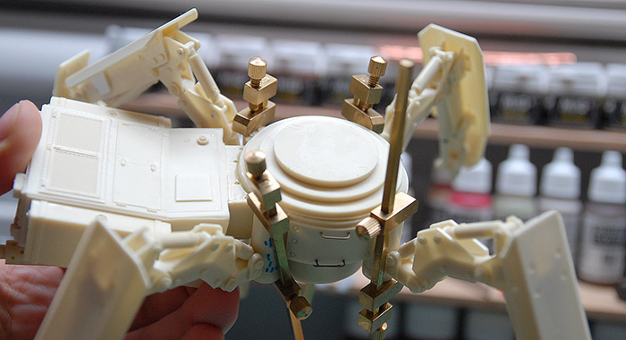
At the end of the last blog post, I had just tacked everything together and tested to be sure it all fit properly. The next step was to solidify all the leg joints and make both models able to support their own weight. So, without further ado, let's get right to it:
Below you can see all of the legs glued in place. For the tan legs on the right, this was a fairly simple matter of cutting the pistons to the correct length and then epoxying them in place. For the grey legs, I left them in place on the base and dripped a bit of thin CA glue into each joint, so that each leg was locked into its correct position.
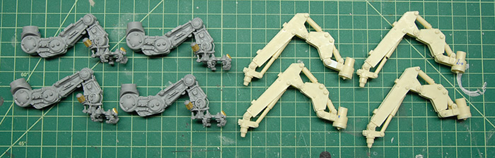
Since that thin layer of CA isn't really going to hold up very well once weight is put on it, I then spent some time drilling holes through each joint and inserting brass rod. The idea was to get the rod all the way through each joint without actually poking out the other side. My hope was that this would give the joints something better than the friction of the CA glue to support them. So far, it has worked very well.
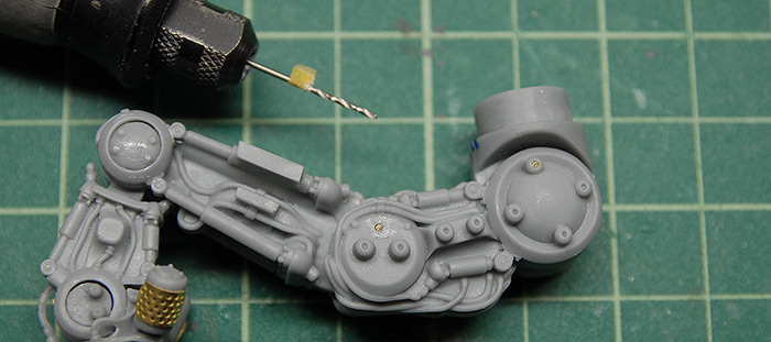
Below you can see a tiny drill bit mounted in the Dremel extension thing (easier to handle in small spaces than the whole Dremel). The little tape tab is there so I know how deep to drill.
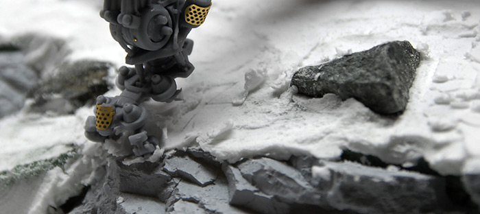
Once the legs were all locked in place, I put a little extra spackle on the base and squished each foot into the ground so that they had little footprints to fit in to. This both made it look like the model is heavy enough that it is digging into the ground and gives me registration marks so that I know exactly where the model is supposed to fit onto the base. Below you can also see a missing toe on this foot. I have no idea where it went! I didn't notice when it broke off and, despite searching all over the place, I couldn't find it. So, I'm just going to put some extra rust there later and pretend like it is supposed to be like that.
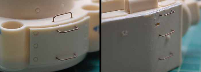
Moving along to the leg armor plates, a number of them called for grab handles. This was just regular old brass rod, bent to shape.
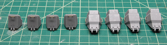
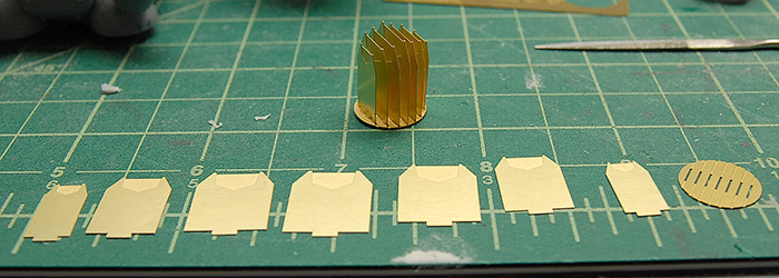
The photo etch that comes with this kit is interesting in that it builds up into large shapes that fit into some of the vents on the upper body of the tank. Below you can see the component parts and assembled collection that fit into the main exhaust tubes.
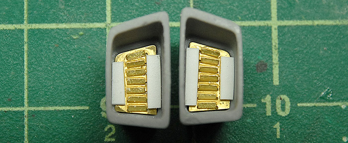
There are similar etch assemblies in the smaller square vents. These fit well, but had the tendency to fall through the holes they were supposed to cover. As you can see below, I just glued on a few strips of styrene in order to give them a little lip on each side and keep them in place.
The instructions also pointed out various places where wire grab handles should be added. Like on the leg armor, these were just simple bent brass wire. In this case, though, the wire that I was using was a bit brittle and tended to snap when bent. In order to soften it up a bit, I annealed it with a torch. For those unfamiliar with this process, I took the brass wire in some pliers (it gets hot!) and slowly passed it through the flame of a butane torch. The goal is to get the metal red hot, but not so hot that it starts to come apart or distort. Letting the metal cool in the air results in a much more pliable bit of wire. The wire is far softer and much easier to bend.
With that done, it was time to start putting everything together. Below you can see the leg armor plates held in place while epoxy cures.
Below you can see the legs clamped in place while the epoxy cures. If you look at the base of the lower left leg, you can see various marks. I put those on there to keep the legs sorted, so that I knew which one went in which spot and at which angle. This should, in theory, result in the legs all being just right when I place the model back on the base.
I say, "in theory" because, after everything was glued and assembled, I placed the model back on the base and the leg that was in the left corner was hovering about 3/8 of an inch off the ground. Not sure if there was a good way to fix it, I decided that that was a good place for a rock!
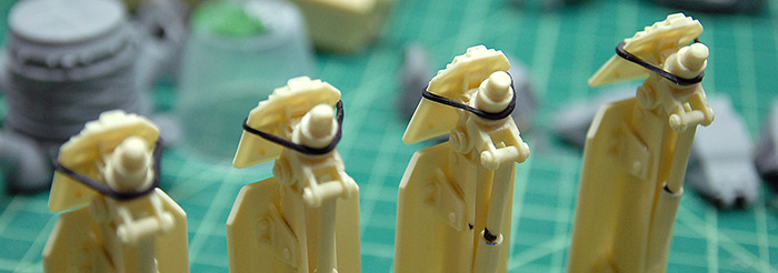
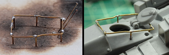
Back on the future-y tank, the kit had come with a photo etch version of a little railing around the hatch. Given the scale, though, this rail seemed much too thin. I decided to have a go at building my own version from some brass rod and solder. I tried a few methods of soldering using the tools that I had, but it was pretty messy and I managed to incinerate a few pieces of rod by accident. What you can see below is the second version (the blackened surface came from the first version). I have since read a brief article in Fine Scale Modeler magazine about working with brass, so the next time I do, I'll be a bit better off. Anyway, with a bit of filing and sanding, some drilling on the resin, and a spot of CA glue, the railing was cleaned up and attached around the hatch.
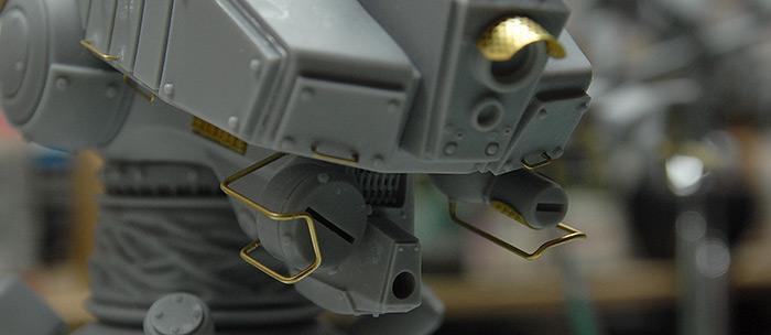
A bit more wire bending got me some protective bars around the sensitive equipment hanging under the front end of this tank.
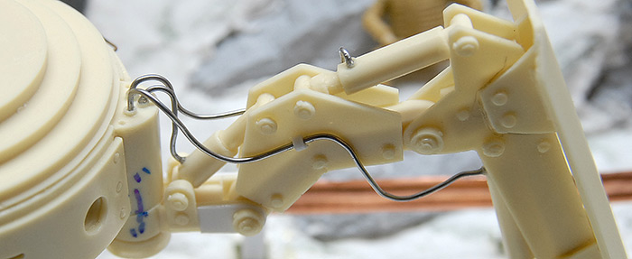
Similarly, the other kit came with some plastic-coated wire to act as hydraulic hosing for the leg pistons. Unfortunately, this wire was not easily shapable and when added, really seemed out of scale. Having just done a bit of soldering on the other tank, I decided to replace the kit wire with some thin solder, since it is so easily shapable. Also, instead of just letting it hang free (which seemed implausible to me, as far as tank design goes), I added a few styrene brackets on the sides of the joint plate, so that it looked like the hosing was held in place.
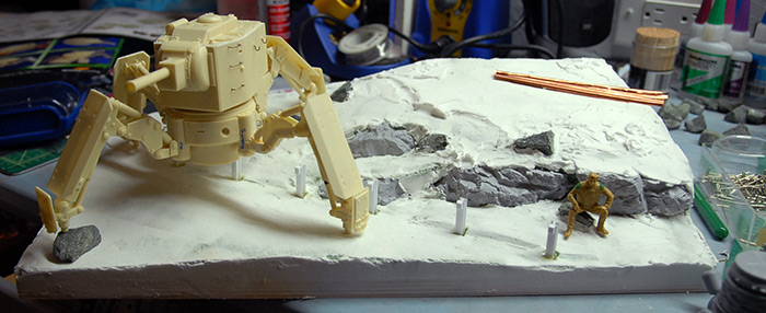
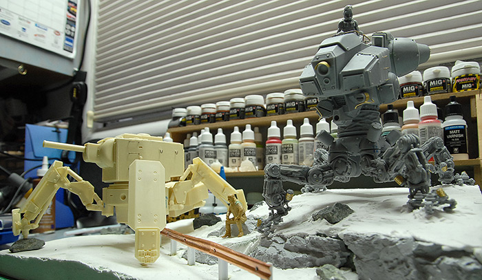
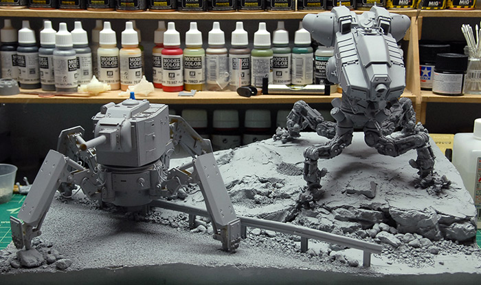
And, with the exception of the gatling gun that goes on the front of the grey tank (and that is fragile!), that wraps up construction on the two models. Below you can see the unprimed models, on the incomplete base.
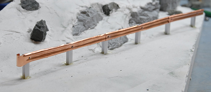
Turning back to the diorama base, it was time to start adding things to it. First was the guard rail. If you recall from the last post, this was made from some sheet copper that I had in a bag of scrap metal bits. In order to attach it to the styrene posts, I just used a small drill bit in the Dremel and drilled through the copper, into the posts. I then made some small bolts out of the top 1/8" of straight pins and used those, with some thick CA, to attach the metal parts.
Next up, it was time to add some different sizes of rocks, gravel and sand in order to start to blend things all together. I picked up a few bags of model railroad decoration from the local hobby shop.

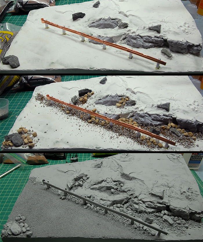
Below you can see the three stages, from clean to primed. I simply worked from large to small. First I added the largest size of rock, clustering them around the base of the hill, then the next size down, clustered around the larger rocks, etc. I decided that the road needed a bit of texture, as the base spackle was just too smooth. I was going with the premise that this bit of road has been long since abandoned, so it wouldn't be super clean and smooth. So what I did was to add a layer of the finest gravel/sand that I had onto the road surface. It ended up a little bit rougher than I had hoped, but I think I'll be able to make up for that with a bit of weathering and dirt on the road later.
With a couple coats of primer on the tanks and base, that should wrap up construction. All that is left now is a great deal of painting and an attempt at flocked grass.
Tune in next time (very soon!) for my attempt at a new (to me) weathering technique and my shot at building a flocking device out of a few cheap parts.
Thanks for reading!
Below you can see all of the legs glued in place. For the tan legs on the right, this was a fairly simple matter of cutting the pistons to the correct length and then epoxying them in place. For the grey legs, I left them in place on the base and dripped a bit of thin CA glue into each joint, so that each leg was locked into its correct position.
Since that thin layer of CA isn't really going to hold up very well once weight is put on it, I then spent some time drilling holes through each joint and inserting brass rod. The idea was to get the rod all the way through each joint without actually poking out the other side. My hope was that this would give the joints something better than the friction of the CA glue to support them. So far, it has worked very well.
Below you can see a tiny drill bit mounted in the Dremel extension thing (easier to handle in small spaces than the whole Dremel). The little tape tab is there so I know how deep to drill.
Once the legs were all locked in place, I put a little extra spackle on the base and squished each foot into the ground so that they had little footprints to fit in to. This both made it look like the model is heavy enough that it is digging into the ground and gives me registration marks so that I know exactly where the model is supposed to fit onto the base. Below you can also see a missing toe on this foot. I have no idea where it went! I didn't notice when it broke off and, despite searching all over the place, I couldn't find it. So, I'm just going to put some extra rust there later and pretend like it is supposed to be like that.
Moving along to the leg armor plates, a number of them called for grab handles. This was just regular old brass rod, bent to shape.
The photo etch that comes with this kit is interesting in that it builds up into large shapes that fit into some of the vents on the upper body of the tank. Below you can see the component parts and assembled collection that fit into the main exhaust tubes.
There are similar etch assemblies in the smaller square vents. These fit well, but had the tendency to fall through the holes they were supposed to cover. As you can see below, I just glued on a few strips of styrene in order to give them a little lip on each side and keep them in place.
The instructions also pointed out various places where wire grab handles should be added. Like on the leg armor, these were just simple bent brass wire. In this case, though, the wire that I was using was a bit brittle and tended to snap when bent. In order to soften it up a bit, I annealed it with a torch. For those unfamiliar with this process, I took the brass wire in some pliers (it gets hot!) and slowly passed it through the flame of a butane torch. The goal is to get the metal red hot, but not so hot that it starts to come apart or distort. Letting the metal cool in the air results in a much more pliable bit of wire. The wire is far softer and much easier to bend.
With that done, it was time to start putting everything together. Below you can see the leg armor plates held in place while epoxy cures.
Below you can see the legs clamped in place while the epoxy cures. If you look at the base of the lower left leg, you can see various marks. I put those on there to keep the legs sorted, so that I knew which one went in which spot and at which angle. This should, in theory, result in the legs all being just right when I place the model back on the base.
I say, "in theory" because, after everything was glued and assembled, I placed the model back on the base and the leg that was in the left corner was hovering about 3/8 of an inch off the ground. Not sure if there was a good way to fix it, I decided that that was a good place for a rock!
Back on the future-y tank, the kit had come with a photo etch version of a little railing around the hatch. Given the scale, though, this rail seemed much too thin. I decided to have a go at building my own version from some brass rod and solder. I tried a few methods of soldering using the tools that I had, but it was pretty messy and I managed to incinerate a few pieces of rod by accident. What you can see below is the second version (the blackened surface came from the first version). I have since read a brief article in Fine Scale Modeler magazine about working with brass, so the next time I do, I'll be a bit better off. Anyway, with a bit of filing and sanding, some drilling on the resin, and a spot of CA glue, the railing was cleaned up and attached around the hatch.
A bit more wire bending got me some protective bars around the sensitive equipment hanging under the front end of this tank.
Similarly, the other kit came with some plastic-coated wire to act as hydraulic hosing for the leg pistons. Unfortunately, this wire was not easily shapable and when added, really seemed out of scale. Having just done a bit of soldering on the other tank, I decided to replace the kit wire with some thin solder, since it is so easily shapable. Also, instead of just letting it hang free (which seemed implausible to me, as far as tank design goes), I added a few styrene brackets on the sides of the joint plate, so that it looked like the hosing was held in place.
And, with the exception of the gatling gun that goes on the front of the grey tank (and that is fragile!), that wraps up construction on the two models. Below you can see the unprimed models, on the incomplete base.
Turning back to the diorama base, it was time to start adding things to it. First was the guard rail. If you recall from the last post, this was made from some sheet copper that I had in a bag of scrap metal bits. In order to attach it to the styrene posts, I just used a small drill bit in the Dremel and drilled through the copper, into the posts. I then made some small bolts out of the top 1/8" of straight pins and used those, with some thick CA, to attach the metal parts.
Next up, it was time to add some different sizes of rocks, gravel and sand in order to start to blend things all together. I picked up a few bags of model railroad decoration from the local hobby shop.
Below you can see the three stages, from clean to primed. I simply worked from large to small. First I added the largest size of rock, clustering them around the base of the hill, then the next size down, clustered around the larger rocks, etc. I decided that the road needed a bit of texture, as the base spackle was just too smooth. I was going with the premise that this bit of road has been long since abandoned, so it wouldn't be super clean and smooth. So what I did was to add a layer of the finest gravel/sand that I had onto the road surface. It ended up a little bit rougher than I had hoped, but I think I'll be able to make up for that with a bit of weathering and dirt on the road later.
With a couple coats of primer on the tanks and base, that should wrap up construction. All that is left now is a great deal of painting and an attempt at flocked grass.
Tune in next time (very soon!) for my attempt at a new (to me) weathering technique and my shot at building a flocking device out of a few cheap parts.
Thanks for reading!
blog comments powered by Disqus